


334 CHAPTER 38: ACCESS MANAGEMENT CONFIGURATION GUIDE
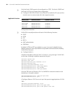
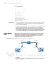
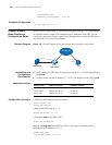
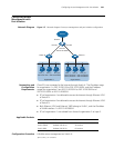
■ Permit all the PCs of organization 1 to access the Internet through Ethernet
1/0/1 on Switch A. Ethernet 1/0/1 carries VLAN 1. The IP address assigned to
the interface of VLAN 1 is 202.10.20.200/24.
■ PCs that do not belong to organization 1, such as PC 2 and PC 3, are not
allowed to access the Internet through Ethernet 1/0/1 on Switch A.
Applicable Products
Configuration Procedure # Enable access management on Switch A.
[SwitchA] am enable
# Configure the IP address of VLAN-interface 1 as 202.10.20.200/24.
[SwitchA] interface Vlan-interface 1
[SwitchA-Vlan-interface1] ip address 202.10.20.200 24
[SwitchA-Vlan-interface1] quit
# Configure an access management IP address pool for Ethernet 1/0/1.
[SwitchA] interface Ethernet 1/0/1
[SwitchA-Ethernet1/0/1] am ip-pool 202.10.20.1 20
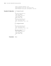
Complete Configuration #
am enable
#
interface Vlan-interface1
ip address 202.10.20.200 255.255.255.0
#
interface Ethernet1/0/1
am ip-pool 202.10.20.1 20
#
Precautions ■ The IP addresses in the access management IP address pool configured for a
port must be on the same segment as the VLAN-interface IP address of the
VLAN to which the port belongs.
■ If the access management IP address pool to be configured for a port contains
an IP address in a static ARP entry of another port, the system will ask you to
delete the ARP entry to ensure that the access management IP address pool
can take effect.
■ To allow only the hosts bound with a port and with their IP addresses in the
access management IP address pool of the port to access external networks,
configure static ARP entries only for IP addresses in the address pool.
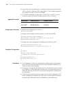
Product series Software version Hardware version
Switch 5500 Release V03.02.04 All versions
Switch 5500G Release V03.02.04 All versions
Switch 4500 Release V03.03.00 All versions