


276 CHAPTER 31: NTP CONFIGURATION GUIDE
<DeviceA> system-view
[DeviceA] interface Vlan-interface 2
[DeviceA-Vlan-interface2] ntp-service multicast-client
■ View the NTP status and NTP session information of Device D after clock
synchronization (You can use the same command to view the NTP status and
NTP session information of Device A).
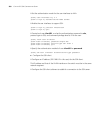
# View NTP status of Device D.
[DeviceD] display ntp-service status
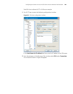
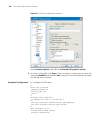
# View NTP session information of Device D.
[DeviceD] display ntp-service sessions
Complete Configuration ■ Configuration on Device C.
#
interface Vlan-interface2
ip address 3.0.1.13 255.255.255.0
ntp-service multicast-server
■ Configuration on Device A.
#
interface Vlan-interface2
ip address 1.0.1.11 255.255.255.0
ntp-service multicast-client
■ Configuration on Device D.
#
interface Vlan-interface2
ip address 3.0.1.14 255.255.255.0
ntp-service multicast-client
Precautions The local clock of the Switch 5500, 5500G, or 4210 cannot be set as a reference
clock. It can synchronize other devices as a reference clock only when its clock is
synchronized.
NTP Client/Server
Mode with
Authentication
Configuration
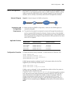
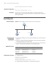
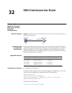
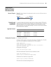
Network Diagram Figure 86 Network diagram for NTP client/server mode with authentication configuration
Networking and
Configuration
Requirements
■ The local clock of Device A is to be used as a reference source, with the stratum
level of 2.
1.0.1.11/24 1.0.1.12/24
Device A Device B