


Configuring PIM-SM plus IGMP plus IGMP Snooping 147
Then, the multicast source sends the multicast traffic along the SPT to the RP.
Upon reaching the RP, the multicast traffic flows down the RPT to the receivers.
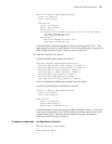
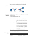
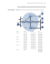
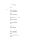
Network Diagram Figure 39 Network diagram for PIM-SM, IGMP, and IGMP Snooping configuration
Device Interface IP address Ports
Switch A Vlan-int100 10.110.1.1/24 Ethernet1/0/1
Vlan-int101 192.168.1.1/24 Ethernet1/0/2
Vlan-int102 192.168.9.1/24 Ethernet1/0/3
Switch B Vlan-int200 10.110.2.1/24 Ethernet1/0/1
Vlan-int103 192.168.2.1/24 Ethernet1/0/2
Switch C Vlan-int200 10.110.2.2/24 Ethernet1/0/1
Vlan-int104 192.168.3.1/24 Ethernet1/0/2
Switch D Vlanint300 10.110.5.1/24 Ethernet1/0/1
Vlanint101 192.168.1.2/24 Ethernet1/0/2
Vlanint105 192.168.4.2/24 Ethernet1/0/3
Switch E Vlanint104 192.168.3.2/24 Ethernet1/0/3
Vlanint103 192.168.2.2/24 Ethernet1/0/2
Vlanint102 192.168.9.2/24 Ethernet1/0/1
Vlanint105 192.168.4.1/24 Ethernet1/0/4
Switch F Vlan100 - Ethernet1/0/1,
Ethernet1/0/2,
Ethernet1/0/3
Ethernet
Ethernet
Source
10.110.5.100/24
PIM-SM
Switch A
Switch B
Switch C
Switch D
Host C
Host D
Receiver
N1
Switch E
Vlan-int200
Vlan-int200
Vlan-int300
Vlan-int102
Vlan-int102
V
l
a
n-i
n
t1
01
V
l
a
n
-i
nt
1
01
Vlan-int103
Vlan-int103
Vlan-int104
Vlan-int104
Vlan-int105
Vlan-int105
Receiver
Host A
Host B
Vlan-int100
Vlan100
Switch F