


70 CHAPTER 13: AUTO DETECT CONFIGURATION GUIDE
■ The master switch remains as master when the detected group is reachable.
■ The priority of the master switch decreases and thus becomes a backup when
the detected group is unreachable.
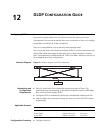
Network Diagram
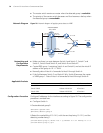
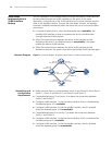
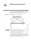
Figure 20 Network diagram of applying auto detect to VRRP
Networking and
Configuration
Requirements
■ Make sure there is a route between Switch A and Switch C, Switch C and
Switch E, Switch B and Switch D, and Switch D and Switch E.
■ Create VRRP group 1 containing Switch A and Switch B, and set the virtual IP
address of the group to 10.1.1.10/24.
■ Normally, data of Host A is forwarded to Host B through Switch A.
■ If the link between Switch C and Switch E fails, Switch B becomes the master
of VRRP group 1. Data of Host A is forwarded to Host B through Switch B.
Applicable Products
Configuration Procedure Configure IP addresses for the interfaces according to Figure 20. The configuration
procedure is omitted here.
■ Configure Switch A
# Create detected group 9.
<SwitchA> system-view
[SwitchA] detect-group 9
# Detect the reachability of 10.1.4.2, with the next hop being 10.1.2.2, and the
detecting number being 1.
[SwitchA-detect-group-9] detect-list 1 ip address 10.1.4.2 nexthop 10.1.2.2
[SwitchA-detect-group-9] quit
Host A
Switch A
Switch B
Virtual IP address:
10.1.1.10/24
Vlan-int2
10.1.1.1/ 24
Vlan-int2
10.1.1.2/24
10.1. 1. 3/24
Vlan-int3
10.1.2.1/24
Vlan-int3
10.1.3.1/24
Vlan-int3
10.1.3.2/24
Vlan-int3
10.1.2.2/24
Switch C
Switch D
Switch E
10.1.4.1/24
10.1.4.2/24
10.1.5.1/24
10.1.5.2/24
Host B
20
.
1.1.1/24
20.1.1.2/24
Product series Software version Hardware version
Switch 5500 Release V03.02.04 All versions
Switch 5500G Release V03.02.04 All versions
Switch 4500 Release V03.03.00 All versions