


NTP Multicast Mode Configuration 275
Precautions The local clock of the Switch 5500, 5500G, or 4210 cannot be set as a reference
clock. It can synchronize other devices as a reference clock only when its clock is
synchronized.
NTP Multicast Mode
Configuration
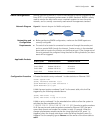
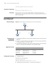
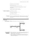
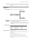
Network Diagram Figure 85 Network diagram for NTP multicast mode configuration
Networking and
Configuration
Requirements
■ The local clock of Device C is to be used as a reference source, with the stratum
level of 2. Set Device C to work in the multicast server mode and send
multicast through its VLAN-interface 2.
■ Device A and Device D are Switch 5500s. Set Device A and Device D to work in
the multicast client mode and listen to multicasts through their VLAN-interface
2 respectively.
Applicable Products
Configuration Procedure
■ Configure Device C.
# Set Device C to work as the multicast server and send multicasts through its
VLAN-interface 2.
<DeviceC> system-view
[DeviceC] interface Vlan-interface 2
[DeviceC-Vlan-interface2] ntp-service multicast-server
■ Configure Device A (perform the same configuration on Device D).
# Set Device A to work as the multicast client and listen multicasts through its
VLAN-interface 2.
Vlan-int2
3.0.1.11/24
Vlan-int2
3.0.1.12/24
Vlan-int2
3.0.1.13/24
Vlan-int2
3.0.1.14/24
Vlan-int2
3.0.1.12/24
Device A Device B
Device C
Device D
Product series Software version Hardware version
Switch 5500 Release V03.02.04 All versions
Switch 5500G Release V03.02.04 All versions
Switch 4500 Release V03.03.00 All versions
Switch 4210 Release V03.01.00 All versions