


254 CHAPTER 27: CLUSTER CONFIGURATION GUIDE
■ The network management interface can be configured on the management
switch only.
n
The network management interface cannot be configured on the Switch 4210.
Cluster Configuration
in Real Networking
In a complicated network, you can manage switches remotely in a bulk through
Switch Clustering, reducing the workload of the network configuration.
After you build a cluster and enable Switch Clustering on the management switch,
and enable NDP and Switch Clustering for the member devices, you can manage
the member switches on the management switch.
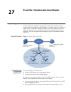
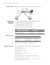
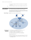
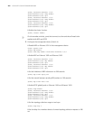
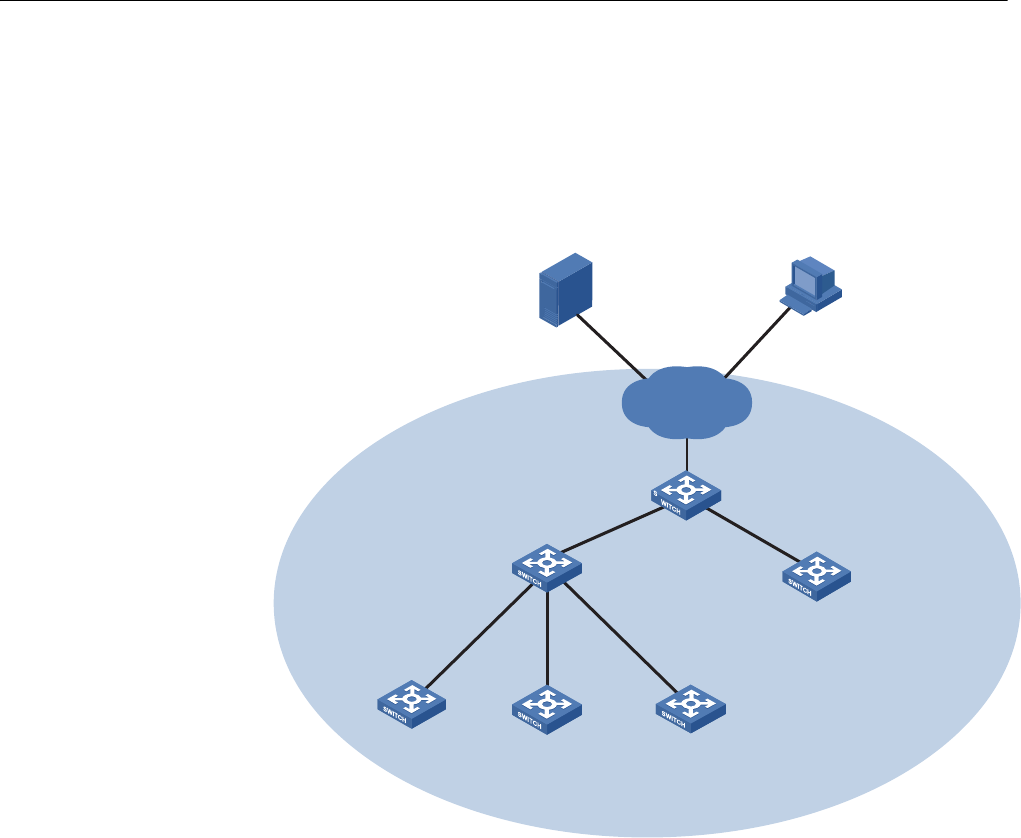
Network Diagram
Figure 76 Network diagram for Switch Clustering cluster
Networking and
Configuration
Requirements
■ The IP address of the management switch (Switch A) is 10.1.1.17.
■ Configure the IP address of the TFTP server as 10.1.1.15.
■ Configure the IP address of the SNMP NMS as 10.1.1.16.
■ The whole cluster shares the same TFTP server and SNMP NMS.
Management switch Switch A:
■ Ethernet 1/0/1 belongs to VLAN 2, whose interface IP address is 163.172.55.1.
■ Two member switches are connected to Ethernet 1/0/1 and Ethernet 1/0/2 of
the management switch.
Switch D
Switch A
Switch B
Switch E
Switch F
10.1.1.15 /24
SNMP host ( NMS
)
10.1. 16/24
Eth 1/0/2
Eth 1/0/3
Eth 1/0/4
Eth 1/0/2
Eth 1/0/3
Eth 1/0/1
TFTP Server
Eth 1/0/1Eth 1/0/1
Eth 1/0/1
Vlan- interface 2
163 .172.55 .1/24
Switch C
Eth 1/0/1
Internet
Cluster
Eth 1/0/1
1.