


156 CHAPTER 16: MULTICAST CONFIGURATION GUIDE
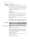
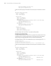
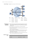
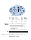
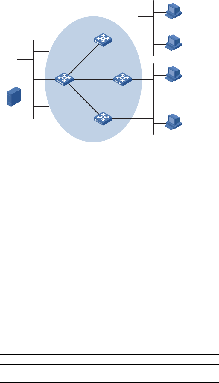
Network Diagram Figure 40 Network diagram for PIM-DM configuration
Networking and
Configuration
Requirements
■ Receivers receive multicast VOD information through multicast. The receiver
groups of different organizations form two stub networks, and at least one
receiver host exists in each stub network. The entire PIM domain operates in
the dense mode.
■ Host A and Host C are multicast receivers in the two stub networks.
■ Switch D connects to the network that comprises the multicast source (Source)
through VLAN-interface 300.
■ Switch A connects to stub network N1 through VLAN-interface 100, and to
Switch D through VLAN-interface 103.
■ Switch B and Switch C connect to stub network N2 through their respective
VLAN-interface 200, and to Switch D through VLAN-interface 101 and
VLAN-interface 102 respectively.
■ IGMPv2 needs to run between Switch A and N1, and also between Switch B,
Switch C, and N2. Typically Switch B acts as the querier.
Application Product
Matrix
Device Interface IP address Device Interface IP address
Switch A Vlan-int100 10.110.1.1/24 Switch D Vlan-int300 10.110.5.1/24
Vlan-int103 192.168.1.1/24 Vlan-int103 192.168.1.2/24
Switch B Vlan-int200 10.110.2.1/24 Vlan-int101 192.168.2.2/24
Vlan-int101 192.168.2.1/24 Vlan-int102 192.168.3.2/24
Switch C Vlan-int200 10.110.2.2/24
Vlan-int102 192.168.3.1/24
Ethernet
EthernetEthernet
Source
10.110.5.100/24
PIM-DM
Switch A
Switch B
Switch C
Switch D
Receiver
Host A
Host B
Host C
Host D
Receiver
N1N2
Vlan-int100
Vlan-int200
Vlan-int200
Vlan-int300 Vlan-int101
Vlan-int101
V
l
a
n
-
i
n
t
1
0
2
V
la
n
-i
n
t
1
0
2
Vl
a
n
-
i
n
t
10
3
V
l
a
n-
i
n
t
10
3
IGMP querier
Product series Software version Hardware version
Switch 5500 Release V03.02.04 All versions
Switch 5500G Release V03.02.04 All versions