


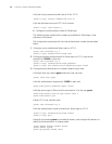


22 CHAPTER 2: VLAN CONFIGURATION GUIDE
[SwitchA-vlan101] quit
[SwitchA] vlan 201
[SwitchA-vlan201] port Ethernet 1/0/2
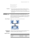
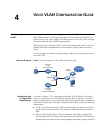
# Configure Ethernet 1/0/3 of Switch A to be a trunk port and to permit the
packets carrying the tag of VLAN 101 or VLAN 201 to pass through.
[SwitchA-vlan201] quit
[SwitchA] interface Ethernet 1/0/3
[SwitchA-Ethernet1/0/3] port link-type trunk
[SwitchA-Ethernet1/0/3] port trunk permit vlan 101 201
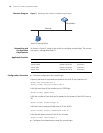
# Create VLAN 101 on Switch B, and add Ethernet 1/0/11 to VLAN 101.
[SwitchB] vlan 101
[SwitchB-vlan101] port Ethernet 1/0/11
# Create VLAN 201 on Switch B, and add Ethernet 1/0/12 to VLAN 201.
[SwitchB-vlan101] quit
[SwitchB] vlan 201
[SwitchB-vlan201] port Ethernet 1/0/12
# Configure Ethernet 1/0/10 of Switch B to be a trunk port and to permit the
packets carrying the tag of VLAN 101 or VLAN 201 to pass through.
[SwitchB-vlan201] quit
[SwitchB] interface Ethernet 1/0/10
[SwitchB-Ethernet1/0/10] port link-type trunk
[SwitchB-Ethernet1/0/10] port trunk permit vlan 101 201
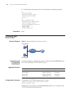
Complete Configuration ■ Configuration on Switch A
#
vlan 101
#
vlan 201
#
interface Ethernet1/0/1
port access vlan 101
#
interface Ethernet1/0/2
port access vlan 201
#
interface Ethernet1/0/3
port link-type trunk
port trunk permit vlan 1 101 201
■ Configuration on Switch B
#
vlan 101
#
vlan 201
#
interface Ethernet1/0/10
port link-type trunk
port trunk permit vlan 1 101 201