


Cluster Configuration in Real Networking 255
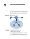
The member switches:
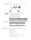
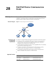
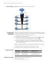
■ Member switch Switch B is connected to Switch D through Ethernet 1/0/2.
■ Switch B is connected to Switch E through Ethernet 1/0/3.
■ Switch B is connected to Switch F through Ethernet 1/0/4.
n
■ Switch A, Switch B and Switch C are usually the Switch 5500 and Switch
5500G.
■ Switch D, Switch E and Switch F can be Switch 5500, Switch 5500Gs, and
Switch 4210.
Applicable Products
Configuration Procedure
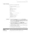
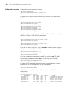
1 Configure the member devices (taking Switch B as an example)
# Enable NDP globally.
<3Com> system-view
[3Com] ndp enable
# Enable NDP on Ethernet 1/0/1, Ethernet 1/0/2, Ethernet1/0/3, and
Ethernet1/0/4.
[3Com] interface Ethernet 1/0/1
[3Com-Ethernet1/0/1] ndp enable
[3Com-Ethernet1/0/1] quit
[3Com] interface Ethernet 1/0/2
[3Com-Ethernet1/0/2] ndp enable
[3Com-Ethernet1/0/2] quit
[3Com] interface Ethernet 1/0/3
[3Com-Ethernet1/0/3] ndp enable
[3Com-Ethernet1/0/3] quit
[3Com] interface Ethernet 1/0/4
[3Com-Ethernet1/0/4] ndp enable
[3Com-Ethernet1/0/4] quit
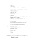
# Enable NTDP globally.
[3Com] ntdp enable
# Enable NTDP on Ethernet 1/0/1, Ethernet 1/0/2, Ethernet1/0/3, and
Ethernet1/0/4.
[3Com] interface Ethernet 1/0/1
[3Com-Ethernet1/0/1] ntdp enable
[3Com-Ethernet1/0/1] quit
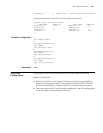
Product series Software version Hardware version
Switch 5500 Release V03.02.04 All versions
Switch 5500G Release V03.02.04 All versions
Switch 4500 Release V03.03.00 All versions
Switch 4210 Release V03.01.00 All versions