


192 CHAPTER 20: VRRP CONFIGURATION GUIDE
Networking and
Configuration
Requirements
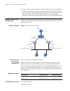
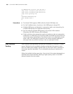
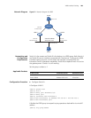
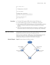
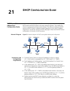
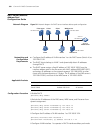
■ There are two switches, the master and the backup, in VRRP group 1.
■ The IP addresses of the master and the backup are 10.100.10.2 and
10.100.10.3 respectively.
■ The master is connected with the upstream network through port Ethernet
1/0/1 that belongs to VLAN 2, and is connected with a Layer 2 switch through
Ethernet 1/0/2 that belongs to VLAN 3.
■ The virtual IP address of the VRRP group is 10.100.10.1.
■ Enable the port tracking function on Ethernet 1/0/1 of the master and specify
that the priority of the master decreases by 50 when Ethernet 1/0/1 fails, which
triggers a new master election in VRRP group 1.
■ On the backup, the configurations related to the upstream and downstream
device connection, and the configurations related to the VRRP group have
been finished. The configuration procedures are omitted here.
Applicable Products
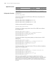
Configuration Procedure Perform the following configurations on the master:
# Enter system view
<3Com> system-view
# Create VLAN 2.
[3Com] vlan 2
[3Com-vlan2] port Ethernet1/0/1
[3Com-vlan2] quit
# Configure VLAN-interface 2.
[3Com] interface Vlan-interface 2
[3Com-Vlan-interface2] ip address 10.100.10.2 255.255.255.0
[3Com-Vlan-interface2] quit
# Create VLAN 3.
[3Com] vlan 3
[3Com-vlan3] port Ethernet1/0/2
[3Com-vlan3] quit
# Configure VLAN-interface 3.
[3Com] interface Vlan-interface 3
[3Com-Vlan-interface3] ip address 10.100.10.4 255.255.255.0
[3Com-Vlan-interface3] quit
# Create VRRP group 1.
Product series Software version Hardware version
Switch 5500 Release V03.02.04 All versions
Switch 5500G Release V03.02.04 All versions