


232 CHAPTER 25: MIRRORING CONFIGURATION GUIDE
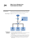
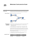
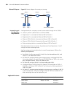
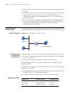
Network Diagram Figure 69 Network diagram for remote port mirroring
Networking and
Configuration
Requirements
The departments of a company connect to each other through Switch 5500s:
■ Switch A, Switch B, and Switch C are Switch 5500s.
■ Department 1 is connected to Ethernet 1/0/1 of Switch A.
■ Department 2 is connected to Ethernet 1/0/2 of Switch A.
■ Ethernet 1/0/3 of Switch A connects to Ethernet 1/0/1 of Switch B.
■ Ethernet 1/0/2 of Switch B connects to Ethernet 1/0/1 of Switch C.
■ Data monitoring device is connected to Ethernet 1/0/2 of Switch C.
The administrator wants to monitor the packets sent from Department 1 and 2
through the data monitoring device.
Use the remote port mirroring function to meet the requirement. Perform the
following configurations:
■ Use Switch A as the source switch, Switch B as the intermediate switch, and
Switch C as the destination switch.
■ On Switch A, create a remote source mirroring group, configure VLAN 10 as
the remote-probe VLAN, ports Ethernet 1/0/1 and Ethernet 1/0/2 as the source
ports, and port Ethernet 1/0/4 as the reflector port.
■ On Switch B, configure VLAN 10 as the remote-probe VLAN.
■ Configure Ethernet 1/0/3 of Switch A, Ethernet 1/0/1 and Ethernet 1/0/2 of
Switch B, and Ethernet 1/0/1 of Switch C as Trunk ports, allowing packets of
VLAN 10 to pass.
■ On Switch C, create a remote destination mirroring group, configure VLAN 10
as the remote-probe VLAN, and configure Ethernet 1/0/2 connected with the
data monitoring device as the destination port.
Applicable Products
Switch A
Eth1/0/3
Dept. 1 Dept. 2
Eth1/0/1
Switch B Switch C
Eth1/0/1 Eth1/0/2
Eth1/0/1
Eth1/0/2
Reflector
port
Eth1/0/4
Eth1/0/2
Data monitoring device
Product series Software version Hardware version
Switch 5500 Release V03.02.04 All versions
Switch 5500G Release V03.02.04 All versions
Switch 4210 All versions