


Configuring Priority Marking and Queue Scheduling 217
Configuring Priority
Marking and Queue
Scheduling
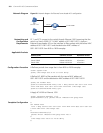
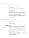
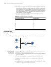
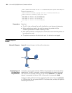
Network Diagram Figure 63 Network diagram for priority marking and queue scheduling configuration
Networking and
Configuration
Requirements
A company uses a switch (a Switch 5500 in this example) to interconnect all the
departments. PC 1, PC 2, and PC 3 are clients. PC 1 and PC 2 are connected to
Ethernet 1/0/1 of the switch; PC 3 is connected to Ethernet 1/0/3 of the switch.
Server 1, Server 2, and Server 3 are the database server, mail server, and file server
of the company. The three servers are connected to Ethernet 1/0/2 of the switch.
Configure priority marking and queue scheduling to satisfy the following
requirements:
■ Configure priority marking on Ethernet 1/0/1 to enable the switch to process
traffic flows from PC 1 and PC 2 to the database server, mail server, and file
server in the descending order.
■ Trust the port priority on Ethernet 1/0/3 and set the port priority of Ethernet
1/0/3 to 5. When PC 1, PC 2, and PC 3 access servers simultaneously, the traffic
from PC 3 is preferentially processed.
Applicable Products
n
The Switch 4210do not support priority marking.
Switch
Eth1/0/1
PC 2
Server 1
192.168.0.1
PC 1
Eth1/0/2
Server 2
Server 3
192.168.0.2
192.168.0.3
PC 3
Eth1/0/3
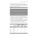
Product series Software version Hardware version
Switch 5500 Release V03.02.04 All versions
Switch 5500G Release V03.02.04 All versions
Switch 4500 Release V03.03.00 All versions
Switch 4210 Release V03.01.00 All versions