


Configuring Multicast VLAN 143
Since multicast packets are transmitted within the multicast VLAN, which is
isolated from user VLANs, the bandwidth and security can be guaranteed.
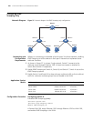
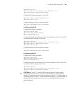
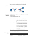
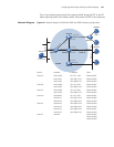
Network Diagram Figure 38 Network diagram for multicast VLAN
Networking and
Configuration
Requirements
Configure the multicast VLAN feature so that Switch A just sends multicast data to
VLAN 10 rather than to each VLAN when Host A and Host B attached to Switch B
need the multicast data.
The following table describes the device details:
Configure VLAN 10 as a multicast VLAN so that users in VLAN 2 and VLAN 3 can
receive multicast packets through VLAN 10.
Application Product
Matrix
W orkStation Sw itchA
SwitchB
Vlan-int 20
168.10.1.1
Eth1/0/1
Eth1/0/10
V
l
a
n
2
V
l
a
n
3
Eth1/0/10
Vlan10
E
t
h
1
/
0
/
1
E
t
h
1
/
0
/
2
HostA
HostB
Vlan-int 10
168.10.2.1
Device Description Remarks
Switch A Layer 3 switch IP address of VLAN-interface 20 is 168.10.1.1. Ethernet
1/0/1 belongs to VLAN 20 and is connected with the
workstation.
IP address of VLAN-interface 10 is 168.10.2.1. Ethernet
1/0/10 belongs to VLAN 10 and is connected with Switch
B.
Switch B Layer 2 switch VLAN 2 contains Ethernet 1/0/1 and VLAN 3 contains
Ethernet 1/0/2. These two ports are connected with Host A
and Host B respectively. The default VLAN of Ethernet
1/0/1 is VLAN 2 and the default VLAN of Ethernet 1/0/2 is
VLAN 3.
VLAN 10 contains Ethernet 1/0/10, Ethernet 1/0/1 and
Ethernet 1/0/2. Ethernet 1/0/10 is connected with Switch
A.
VLAN 10 is multicast VLAN. Ethernet 1/0/1 sends packets
of VLAN 2 and VLAN 10 without VLAN tags.
Ethernet 1/0/2 sends packets of VLAN 3 and VLAN 10
without VLAN tags.
HostA User 1 Connected with Ethernet 1/0/1 of Switch B
HostB User 2 Connected with Ethernet 1/0/2 of Switch B
Product series Software version Hardware version
Switch 5500 Release V03.02.04 All versions
Switch 5500G Release V03.02.04 All versions
Switch 4500 Release V03.03.00 All versions