


190 CHAPTER 20: VRRP CONFIGURATION GUIDE
# Create VRRP group 1.
[LSW-A] interface Vlan-interface 2
[LSW-A-Vlan-interface2] vrrp vrid 1 virtual-ip 202.38.160.111
# Set the priority of Switch A in VRRP group 1 to 110.
[LSW-A-Vlan-interface2] vrrp vrid 1 priority 110
# Set the interface to be tracked.
[LSW-A-Vlan-interface2] vrrp vrid 1 track interface Vlan-interface 3
reduced 30
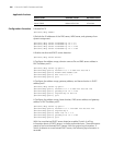
■ Configure Switch B.
# Configure VLAN 2.
<LSW-B> system-view
[LSW-B] vlan 2
[LSW-B-vlan2] port Ethernet1/0/5
[LSW-B-vlan2] quit
[LSW-B] interface Vlan-interface 2
[LSW-B-Vlan-interface2] ip address 202.38.160.2 255.255.255.0
[LSW-B-Vlan-interface2] quit
# Enable a VRRP group to respond to ping operations destined for its virtual IP
address.
[LSW-B] vrrp ping-enable
# Create VRRP group 1.
[LSW-B] interface Vlan-interface 2
[LSW-B-Vlan-interface2] vrrp vrid 1 virtual-ip 202.38.160.111
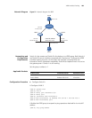
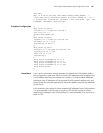
Normally, Switch A acts as the gateway. When VLAN-interface 3 on Switch A
becomes unavailable, the priority of Switch A decreases by 30, making the priority
of Switch A lower than that of Switch B. Therefore, Switch B preempts and
becomes the master to act as the gateway.
When VLAN-interface 3 resumes to work, Switch A becomes the master again to
act as the gateway.
Complete Configuration
■ Configuration on Switch A
#
vrrp ping-enable
#
interface Vlan-interface2
ip address 202.38.160.1 255.255.255.0
vrrp vrid 1 virtual-ip 202.38.160.111
vrrp vrid 1 priority 110
vrrp vrid 1 track Vlan-interface1 reduced 30
#
interface Ethernet1/0/6