


144 CHAPTER 16: MULTICAST CONFIGURATION GUIDE
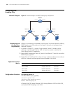
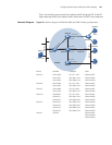
Configuration Procedure Assume that the IP addresses have been configured and the devices have been
connected correctly.
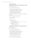
1 Configure Switch A.
# Configure the IP address of VLAN-interface 20 as 168.10.1.1, and enable
PIM-DM.
<SwitchA> system-view
[SwitchA] multicast routing-enable
[SwitchA] vlan 20
[SwitchA-vlan20]port Ethernet1/0/1
[SwitchA-vlan20] quit
[SwitchA] interface Vlan-interface 20
[SwitchA-Vlan-interface20] ip address 168.10.1.1 255.255.255.0
[SwitchA-Vlan-interface20] pim dm
[SwitchA-Vlan-interface20] quit
# Create VLAN 10.
[SwitchA] vlan 10
[SwitchA-vlan10] quit
# Configure Ethernet 1/0/10 as a Hybrid port, assign it to VLAN 10, and configure
it to send packets of VLAN 10 with the VLAN tag kept.
[SwitchA] interface Ethernet1/0/10
[SwitchA-Ethernet1/0/10] port link-type hybrid
[SwitchA-Ethernet1/0/10] port hybrid vlan 10 tagged
[SwitchA-Ethernet1/0/10] quit
# Configure the IP address of VLAN-interface 10 as 168.10.2.1, and enable
PIM-DM and IGMP.
[SwitchA] interface Vlan-interface 10
[SwitchA-Vlan-interface10] ip address 168.10.2.1 255.255.255.0
[SwitchA-Vlan-interface10] igmp enable
[SwitchA-Vlan-interface10] pim dm
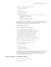
2 Configure Switch B.
# Enable IGMP Snooping globally.
<SwitchB> system-view
[SwitchB] igmp-snooping enable
# Create VLAN 2, VLAN 3, and VLAN 10, configure VLAN 10 as a multicast VLAN,
and enable IGMP Snooping in VLAN 10.
[SwitchB] vlan 2 to 3
Please wait.... Done.
[SwitchB] vlan 10
[SwitchB-vlan10] service-type multicast
Switch 4210 Release V03.01.00 All versions
Product series Software version Hardware version