


210 CHAPTER 22: ACL CONFIGURATION GUIDE
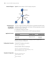
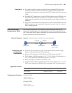
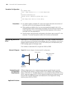
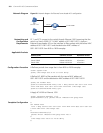
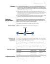
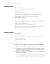
Network Diagram Figure 60 Network diagram for Ethernet frame header ACL configuration
Networking and
Configuration
Requirements
PC 1 and PC 2 connect to the switch through Ethernet 1/0/1 (assuming that the
switch is a Switch 5500). PC 1’s MAC address is 0011-0011-0011. Apply an
Ethernet frame header ACL on the interface to filter packets with the source MAC
address of 0011-0011-0011 and the destination MAC address of
0011-0011-0012 from 8:00 to 18:00 everyday.
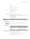
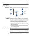
Applicable Products
Configuration Procedure # Define a periodic time range that is from 8:00 to 18:00 everyday.
<3Com> system-view
[3Com] time-range test 8:00 to 18:00 daily
# Define ACL 4000 to filter packets with the source MAC address of
0011-0011-0011 and the destination MAC address of 0011-0011-0012.
[3Com] acl number 4000
[3Com-acl-ethernetframe-4000] rule 1 deny source 0011-0011-0011 ffff
-ffff-ffff dest 0011-0011-0012 ffff-ffff-ffff time-range test
[3Com-acl-ethernetframe-4000] quit
# Apply ACL 4000 to Ethernet 1/0/1.
[3Com] interface Ethernet 1/0/1
[3Com-Ethernet1/0/1] packet-filter inbound link-group 4000
Complete Configuration #
acl number 4000
rule 1 deny source 0011-0011-0011 ffff-ffff-ffff dest 0011-0011-001
2 ffff-ffff-ffff time-range test
#
interface Ethernet1/0/1
packet-filter inbound link-group 4000 rule 1
#
time-range test 08:00 to 18:00 daily
#
Switch
Eth1/0/1
PC 1
0011-0011-0011
PC 2
To the route
r
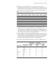
Product series Software version Hardware version
Switch 5500 Release V03.02.04 All versions
Switch 5500G Release V03.02.04 All versions
Switch 4500 Release V03.03.00 All versions