202
www.gateway.com
Chapter 7: Troubleshooting
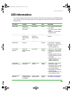
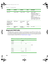
Diagnostic POST LEDs
The BIOS sends a code (in raw binary) to port 80 prior to each POST task. These codes
are displayed on eight LEDs, located on the system board, which can be read by the user
and can provide troubleshooting information in the event of a system hang during POST.
For the location of these LEDs, see “System board” on page 5.
Power supply
status (3)
Power supply
module status
On each power
supply module
Green and
Orange
Top LED (green) - On means
power is good
Middle LED (orange) - On
means there is a fault
condition in this power supply
module
Bottom LED (green) - On
means that AC power to this
power supply module is OK.
POST Code
diagnostic LEDs
0-7 (LSB, bit1,
bit2, bit3, bit4, bit5,
bit6, MSB) bottom
to top
Display boot 80
POST code
On the left back
of the system
board
Each LED
can be
Off,
Green,
Orange,
or Red
See Post Code Table below
Fan fault Indicate fan
failure
On each
hot-swap fan
Orange On = Fault
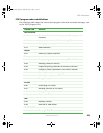
LED reference designator Bit Example: Initialize memory
DS7D2 7 (MSB)
0x27
DS7D3 6
DS7D4 5 On
DS7D5 4
DS7D6 3
DS7D1 2 On
DS7D2 1 On
DS7D3 0 (LSB) On
LED Name Function Location Color Description
8510702.book Page 202 Thursday, July 7, 2005 11:21 AM


