


176 Other Settings
Chapter 9 System Settings
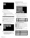
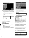
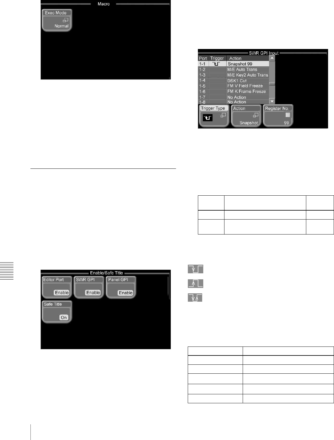
The Macro menu appears.
2
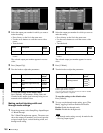
Press [Exec Mode].
A popup window appears.
3
Select the macro execution mode.
Normal: Execution of the next event starts
automatically when a macro event finishes
executing.
Step: Execution pauses when a macro event finishes
executing.
GPI Input/Output Setup (GPI Menu)
Use the GPI menu to set up GPI signal inputs and outputs
between the switcher, control panel or DCU (MKS-8700/
2700) and external devices.
To enable GPI input to the switcher or control
panel
You need to enable GPI input before you can use GPI input
signals. Do this in the Enable/Safe Title menu.
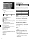
1
From the top menu, select Misc >Enable/Safe Title.
The Enable/Safe Title menu appears.
2
Press the button for the type of GPI input to enable.
To enable GPI input to the control panel: Press
[Panel GPI], setting it to [Enable].
To enable GPI input to the switcher: Press [SWR
GPI], setting it to [Enable].
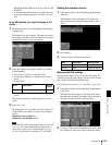
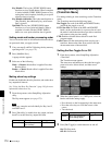
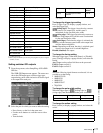
Setting switcher GPI inputs
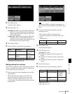
1
From the top menu, select Setup/Diag >GPI >SWR
GPI In.
The SWR GPI Input menu appears. The status area
shows the GPI input ports, and the trigger type and
action set for the signal to be input to each port.
2
Select the port for which you want to make the setting.
• Press directry on the list in the status area.
• Use the arrow buttons to scroll the reverse video
cursor.
• Turn the knobs. (E.g.: if the setting by knob 1 is
value 5 and the setting by knob 2 is value 1, this is
shown as 5-1.)
To change the trigger type setting
Press [Trigger Type], to display a popup window, and
select the trigger type.
(falling edge): Trigger is applied on the falling edge
of an input
pulse.
(rising edge): Trigger is applied on the rising edge
of an input
pulse.
(both edges): Trigger is applied on both falling and
rising edges
of an input pulse.
Disable (disabled): Input pulses are ignored.
To change the action setting
Press [Action], to display a popup window, and select the
action.
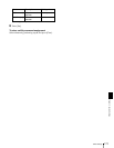
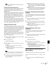
Knob Description Setting
values
1 (Port) GPI input port number selection 1 to 8
2 (No) Number selection to which action
is to be assigned
1 to 8
Action button Status area display
M/E Auto Trans M/E AT
M/E Cut M/E Cut
P/P Auto Trans
a)
P/P AT
P/P Cut
a)
P/P Cut
M/E Key1 Auto Trans M/E K1 AT