


182 Other Settings
Chapter 9 System Settings
2
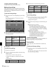
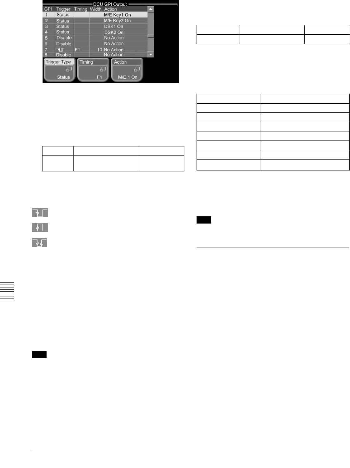
Using any of the following methods, select the GPI
output to set.
• Press directry on the list in the status area.
• Use the arrow buttons to scroll the reverse video
cursor.
• Turn the knob.
To change trigger type settings
Press [Trigger Type] to display a popup window, then
select the trigger type.
(falling edge): Trigger is applied on the falling
edge of an input pulse.
(rising edge): Trigger is applied on the rising edge
of an input pulse.
(both edges): Trigger is applied on both falling and
rising edges of an input pulse.
Status: Trigger is applied when the relay status changes to
open or closed, or when the level changes to low or
high.
Disable (disabled): Input pulses are ignored.
To change output timings
When the trigger type is other than [Status] or [Disable],
you can press [Timing] to display a popup window and
select from the following timings.
Any: Output on the earliest field that can be processed.
Field 1: Output on field 1.
Field 2: Output on field 2.
Note
You cannot set the timing when any of the following signal
formats are selected.
• 1080PsF/23.976
• 1080PsF/24
• 1080PsF/25
• 1080PsF/29.97
• 720P/59.94
To change pulse widths
When the trigger type is other than [Status] or [Disable],
turn knob 2 to set the pulse width.
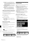
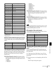
To change action settings
When the trigger type is [Status], you can press [Action] to
display a popup window and select from the actions shown
in the following table.
a) When [Editor GPI ?] is selected, press [GPI No] and select an Editor GPI
number (1 to 32).
When the trigger type is other than [Status], the only
possible selections are [No Action] and [Editor GPI ?].
Note
[Editor GPI ?] can be used only when you have a valid
license for the BZS-8050 Editing Control Software.
Tally Setup (System Tally Menu)
For details of the setup for tally signals to be output from
the switcher to external devices, see “Setting switcher GPI
outputs” in the section “GPI Input/Output Setup (GPI
Menu)” (page 176).
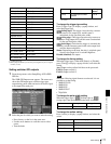
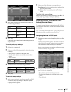
Use the System Tally menu to make settings related to
system tally.
Assigning switcher inputs and outputs to
the S-Bus space
The MFS-2000 system uses the S-Bus protocol as its
interface to routers (routing switchers). Therefore it is
necessary to assign inputs and outputs of the switcher
and so on to an S-Bus space.
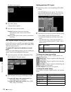
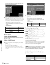
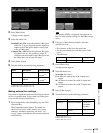
1
From the top menu, select Setup/Diag >System Tally
>S-Bus Assign.
The S-Bus Assign menu appears. The status area
shows the matrix size, source addresses, destination
addresses, and levels.
Knob Description Setting values
1 (GPI) GPI output number
selection
1 to 50
Knob Description Setting values
2 (Pulse Width) Pulse width 1 to 60 (fields)
Operating button Status area display
M/E Key1 On M/E K1 On
M/E Key2 On M/E K2 On
DSK1 On DSK1 On
DSK2 On DSK2 On
Error Error
No Action No Action
Editor GPI ?
a)
Editor GPI