


OSPF 101
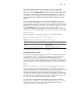
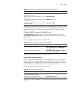
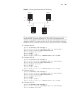
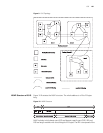
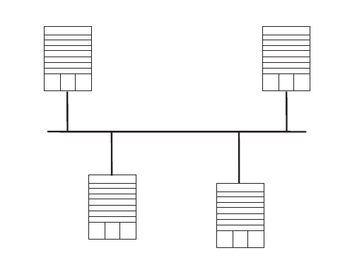
Figure 6 Configuring DR Election Based on OSPF Priority
The commands listed in the following examples enable Switch A and Switch C to
be DR and BDR. The priority of Switch A is 100, which is the highest on the
network, so it is elected as the DR. Switch C has the second highest priority, so it is
elected as the BDR. The priority of Switch B is 0, which means that it cannot be
elected as the DR, and Switch D does not have a priority, which takes 1 by default.
1 Configure Switch A:
[Switch A]interface Vlan-interface 1
[Switch A-Vlan-interface1]ip address 196.1.1.1 255.255.255.0
[Switch A-Vlan-interface1]ospf dr-priority 100
[Switch A]router id 1.1.1.1
[Switch A]ospf
[Switch A-ospf-1]area 0
[Switch A-ospf-1-area-0.0.0.0]network 196.1.1.0 0.0.0.255
2 Configure Switch B:
[Switch B]interface Vlan-interface 1
[Switch B-Vlan-interface1]ip address 196.1.1.2 255.255.255.0
[Switch B-Vlan-interface1]ospf dr-priority 0
[Switch B]router id 2.2.2.2
[Switch B]ospf
[Switch B-ospf-1]area 0
[Switch B-ospf-1-area-0.0.0.0]network 196.1.1.0 0.0.0.255
3 Configure Switch C:
[Switch C]interface Vlan-interface 1
[Switch C-Vlan-interface1]ip address 196.1.1.3 255.255.255.0
[Switch C-Vlan-interface1]ospf dr-priority 2
[Switch C]router id 3.3.3.3
[Switch C]ospf
[Switch C-ospf-1]area 0
[Switch C-ospf-1-area-0.0.0.0]network 196.1.1.0 0.0.0.255
4 Configure Switch D:
[Switch D]interface Vlan-interface 1
[Switch D-Vlan-interface1]ip address 196.1.1.4 255.255.255.0
[Switch D]router id 4.4.4.4
Switch A
1.1.1.1
DR
Switch D
4.4.4.4
Switch B
2.2.2.2
Switch C
3.3.3.3
BDR
196.1.1.4/24
196.1.1.3/24196.1.1.2/24
196.1.1.1/24