


148 CHAPTER 5: IP ROUTING PROTOCOL OPERATION
[Switch C]bgp 200
[Switch C-bgp]group rr internal
[Switch C-bgp]peer rr reflect-client
[Switch C-bgp]peer 193.1.1.2 group rr
[Switch C-bgp]peer 194.1.1.2 group rr
4 Configure Switch D:
a Configure VLAN 4:
[Switch D]interface vlan-interface 4
[Switch D-Vlan-interface4]ip address 194.1.1.2 255.255.255.0
b Configure BGP peers
[Switch D]bgp 200
group in internal
[Switch D-bgp]peer 194.1.1.1 group in
Using the display bgp routing-table command, you can view BGP routing table
on Switch B. Note that Switch B knows of the existence of network 1.0.0.0.
Using the display bgp routing-table command, you can view the BGP routing
table on Switch D. Note that Switch D also knows the existence of network
1.0.0.0.
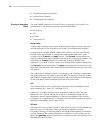
Configuring BGP Routing
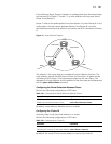
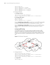
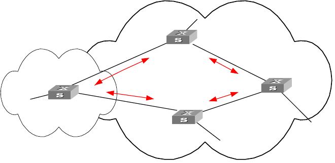
This example illustrates how the administrators manage the routing via BGP
attributes. All switches are configured with BGP, and IGP in AS 200 uses OSPF.
Switch A is in AS 100, and acts as Switch B of AS 200 and BGP neighbor of Switch
C. Both Switch B and Switch C operate IBGP to Switch D. Switch D is also in AS
200.
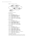
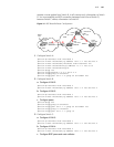
Figure 15 BGP Routing Configuration
1 Configure Switch A:
[Switch A]interface Vlan-interface 2
[Switch A-Vlan-interface2]ip address 192.1.1.1 255.255.255.0
[Switch A]interface Vlan-interface 3
[Switch A-Vlan-interface3]ip address 193.1.1.1 255.255.255.0
a Enable BGP
[Switch A]bgp 100
VLAN 4
194.1.1.2/24
VLAN 2
192.1.1.1/24
VLAN 3
193.1.1.1/24
VLAN 3
193.1.1.2/24
VLAN 5
195.1.1.2/24
VLAN 2
192.1.1.2/24
2.2.2.2
4.4.4.4
3.3.3.3
1.1.1.1
AS100
AS200
VLAN 4
194.1.1.1/24
VLAN 5
195.1.1.1/24
IBGP
IBGP
EBGP
EBGP
To network
1.0.0.0
To network
2.0.0.0
To network
4.0.0.0
To network
3.0.0.0
Switch A
Switch B
Switch C
Switch D