


Configuring VRRP 297
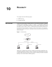
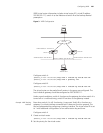
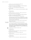
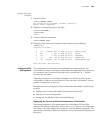
VRRP virtual router information includes virtual router ID1, virtual IP address
202.38.160.111, switch A as the Master and switch B as the backup allowed
preemption.
Figure 3 VRRP Configuration
Configure switch A:
[SW8800_A-vlan-interface2]vrrp vrid 1 virtual-ip 202.38.160.111
[SW8800_A-vlan-interface2]vrrp vrid 1 priority 110
Configure switch B:
[SW8800_B-vlan-interface2]vrrp vrid 1 virtual-ip 202.38.160.111
The virtual router can be used after all routers in the group are configured. The
host A default gateway should be configured as 202.38.160.111.
Under normal conditions, switch A functions as the gateway, but when switch A is
turned off or is malfunctioning, switch B functions as the gateway instead.
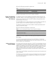
Example: VRRP Tracking
Interface
Even when switch A is still functioning, it may want Switch B to function as a
gateway if a critical interface connected with it does not function properly. This
can be implemented by configuring a tracking interface. The virtual router ID is set
to 1 with additional configurations of an authorization key and timer.
Configure switch A
1 Create a virtual router.
[SW8800_A-vlan-interface2]vrrp vrid 1 virtual-ip 202.38.160.111
2 Set the priority for the virtual router.
10.2.3.1
Host B
Internet
Switch B
VLAN-interface3: 10.100.10.2
Switch A
VLAN-interface2: 202.38.160.2
Virtual IP address: 202.38.160.111
202.36.160.3
VLAN-interface2: 202.38.160.1
Host A