


292 CHAPTER 10: RELIABILITY
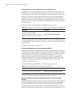
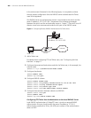
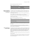
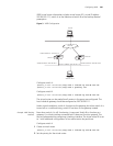
Figure 2 Virtual Router
This virtual router has its own IP address: 10.100.10.1, which can be the actual
interface address of a switch within the virtual router. The switches within the
virtual router have their own IP addresses, such as 10.100.10.2 for the Master
switch and 10.100.10.3 for the BACKUP switch. The hosts on the LAN use the IP
address of this virtual router 10.100.10.1, but not the specific IP addresses
10.100.10.2 of the master switch and 10.100.10.3 of the backup switch. The
default routes for the hosts on this LAN are configured using the IP address of this
virtual router 10.100.10.1 as their gateway. Therefore, hosts within the network
communicate with the external network through this virtual router. If a master
switch in the virtual router group breaks down, the backup switch functions as the
new master switch. This avoids interrupting communication between the hosts
and external networks.
Configuring VRRP VRRP configuration tasks are described in the following sections:
■ Enable Pinging the Virtual IP Address
■ Setting Correspondence Between Virtual IP and MAC Addresses
■ Adding and Deleting a Virtual IP Address
■ Configuring the Priority of Switches
■ Configuring Preemption and Delay for a Switch
■ Configuring Authentication Type and Authentication Key
■ Configuring the VRRP Timer
■ Configuring a Switch to Track an Interface
Enable Pinging the
Virtual IP Address
This operation enables or disables ping response for the virtual IP address of the
backup group. The standard VRRP protocol does not support ping response.
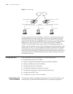
Network
Actual IP address 10.100.10.2
Master
Actual IP address 10.100.10.3
Backup
Virtual IP address 10.100.10.1Virtual IP address 10.100.10.1 Ethernet
Host 1 Host 2
Host 3
10.100.10.7
10.100.10.8
10.100.10.9