


102 CHAPTER 5: IP ROUTING PROTOCOL OPERATION
[Switch D]ospf
[Switch D-ospf-1]area 0
[Switch D-ospf-1-area-0.0.0.0]network 196.1.1.0 0.0.0.255
On Switch A, execute the display ospf peer command to display the OSPF
neighbors. Note that Switch A has three neighbors.
The state of each neighbor is full, which means that adjacency is set up between
Switch A and each neighbor. Switch A and Switch C should set up adjacencies
with all the routers on the network so that they can serve as the DR and BDR on
the network. Switch A is DR, while Switch C is BDR on the network, and all the
other neighbors are DR others (which means that they are neither DRs nor BDRs).
5 Modify the priority of Switch B to 200:
[Switch B-Vlan-interface2000]ospf dr-priority 200
In Switch A, execute the display ospf peer command to show its OSPF
neighbors. Note that the priority of Switch B has been modified to 200, but it is
still not the DR.
Only when the current DR is offline, does the DR change. Shut down Switch A,
and run the display ospf peer command on Switch D to display its neighbors.
Note that the original BDR (Switch C) becomes the DR, and Switch B is the BDR
now.
If all switches on the network are removed and added again, Switch B is elected as
the DR (with the priority of 200), and Switch A becomes the BDR (with a priority of
100). To switch off and restart all the switches initiates a new round of DR and
BDR selection.
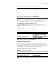
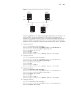
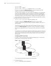
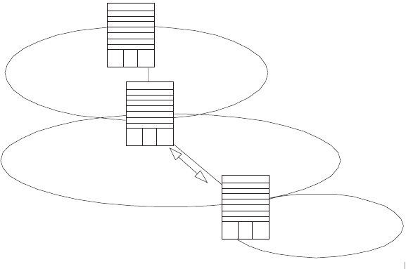
Configuring OSPF Virtual Links
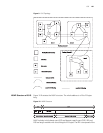
In Figure 7, Area 2 and Area 0 are not directly connected. Area 1 is used as the
transit area for connecting Area 2 and Area 0.
Figure 7 OSPF Virtual Link Configuration
The commands listed below implement this configuration.
1 Configure Switch A:
[Switch A]interface Vlan-interface 1
Switch A
1.1.1.1
Switch B
2.2.2.2
Switch C
3.3.3.3
Virtual
Link
Area 0
Area 1
Area 2
197.1.1.2/24
197.1.1.1/24
196.1.1.2/24
196.1.1.1/24
152.1.1.1/24