


104 CHAPTER 5: IP ROUTING PROTOCOL OPERATION
peer router, it indicates that faults have occurred to the physical link and the
lower level protocol.
■ If the physical link and the lower layer protocol are normal, check the OSPF
parameters configured on the interface. The parameters should be the same
parameters configured on the router adjacent to the interface. The same
area ID should be used, and the networks and the masks should also be
consistent. (The P2P or virtually linked segment can have different segments
and masks.)
■ Insure that the dead timer on the same interface is at least four times the
value of the hello timer.
■ If the network type is NBMA, the peer must be manually specified, using the
peer ip-address command.
■ If the network type is broadcast or NBMA, there must be at least one
interface with a priority greater than zero.
■ If an area is set as the STUB area to which the routers are connected, the
area on these routers must also be set as a STUB area.
■ The same interface type should be adopted for the neighboring routers.
■ If more than two areas are configured, at least one area should be
configured as the backbone area with an area ID of 0.
■ Ensure that the backbone area connects with all other areas.
■ The virtual links cannot pass through the STUB area.
■ Troubleshooting globally
If OSPF cannot discover remote routes and OSPF has been configured
according to the previous procedures, and you have checked all local
troubleshooting items, verify the following configurations.
■ If more than two areas are configured on a router; at least one area should
be configured as the backbone area.
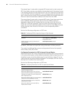
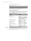
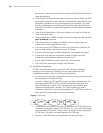
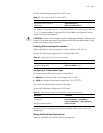
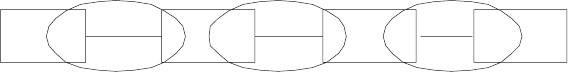
As shown in Figure 8, RTA and RTD are each configured to belong to only
one area, whereas RTB and RTC are both configured to belong to two
areas. RTB belongs to area0, which complies with the backbone area
membership requirement. However, RTC does not belong to area0.
Therefore, a virtual link must be set up between RTC and RTB to insure that
area2 and area0 (the backbone area) are connected.
Figure 8 OSPF Areas
■ The backbone area (area0) cannot be configured as the STUB area and the
virtual link cannot pass through the STUB area. So, if a virtual link has been
set up between RTB and RTC, neither area1 nor area0 can be configured as
a STUB area. Only area2 can be configured as a STUB area.
■ Routers in the STUB area cannot redistribute the external routes.
RTA
RTB
RTC
RTD
area0
area1
area2