


38 CHAPTER 2: PORT CONFIGURATION
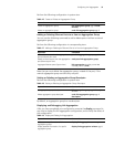
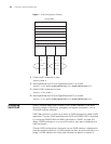
Example: Link
Aggregation
Configuration
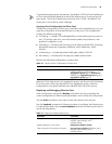
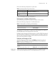
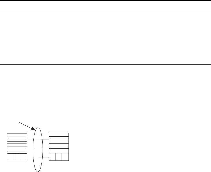
Switch A connects switch B with three aggregation ports, numbered as
GigabitEthernet2/1/1 to GigabitEthernet2/1/3, so that the incoming and outgoing
loads can be balanced among the member ports.
Figure 2 Networking For Link Aggregation
The following code example lists only the configuration for switch A. The
configuration for switch B is similar.
1 Configure aggregation group 1.
[SW8800]link-aggregation group 1 mode manual
Add Ethernet ports GigabitEthernet2/1/1 to GigabitEthernet2/1/3 into
aggregation group 1.
[SW8800]interface gigabitethernet2/1/1
[SW8800-GigabitEthernet2/1/1]port link-aggregation group 1
[SW8800-GigabitEthernet2/1/1]interface ethernet2/1/2
[SW8800-GigabitEthernet2/1/2]port link-aggregation group 1
[SW8800-GigabitEthernet2/1/2]interface ethernet2/1/3
[SW8800-GigabitEthernet2/1/3]port link-aggregation group 1
Display detailed link aggregation information
at the port
display link-aggregation interface {
interface-type interface-number |
interface-name } [ to { interface-type
interface-num | interface-name } ]
Disable/enable debugging link aggregation
errors
[ undo ] debugging link-aggregation error
Disable/enable debugging link aggregation
events
[ undo ] debugging link-aggregation
event
Table 19 Display and Debug Link Aggregation (continued)
Operation Command
Link aggregation
Switch A Switch B