


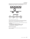
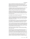
Figure 19 on page 260 shows the areas that intersect are areas 1 and 2. The
remainder of the areas can be duplicated between the two domains. In the
example, there are two areas 3, 4, and 5, one in each domain. Note that it is never
possible to allow direct connection between a node in area 3 in domain A and area
3 in domain B. The best that you can do is give the areas in the intersection the
ability to talk to portions of each domain.
In designing the intersection, be careful that neither domain relies on routes through
the intersection to maintain connectivity between areas that are not in the
intersection. Because the routes in and out of the intersection are filtered, they
probably do not offer normal reachability between all areas in the domain.
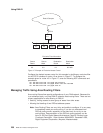
To decide how to configure the routing filters, draw a concise map of the
configuration. On this map, locate all of the areas and outline the two domains.
Then decide upon the filtering fence that you need to establish. Carefully go around
the intersection of the two domains and locate all level 2 adjacencies that cross the
filtering fence. These are one hop communications paths between level 2 routers
that cross between areas.
In the example, there are six adjacencies that cross the fence, 1.18 to 5.7, 1.18 to
5.8, 1.18 to 8.3, 2.17 to 3.12, 2.21 to 4.7, and 2.21 to 4.9.
The first step in designing the area filters is to set up filters that keep the areas in
one domain from being propagated into the other domain. The only area routes that
should leave the intersection are those for areas in the intersection. In the example,
these are areas 1 and 2. Therefore, only routes for areas 1 and 2 should be sent
from nodes such as 2.17 and 3.12.
On point-to-point links such as 2.17 and 3.12, it does not matter which end filters,
but it is probably safer to filter on the sending end. Therefore there would be a filter
on the interface of 2.17, allowing forwarding only routes from areas 1 and 2. The
same would occur on the two interfaces of 2.21 and the link from 1.18 and 8.3.
When the hop between two areas is an Ethernet or other broadcast media, such as
1.18 to 5.7 and 5.8, you should make the decision on another basis. Most Ethernets
have most of the level 2 routing nodes in one area, and a few in the second area.
Here, the filtering should be on the few, rather than the many. In the example, node
1.18 is the interloper on the Ethernet in area 5, so it should filter. Mode 1.18 would
send routers only for areas 1 and 2 on the Ethernet.
You can filter on both ends of an adjacency. This adds an extra layer of security
against accidental reconfiguration. However, if you set up only one end for filtering,
then only that end filters.
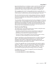
Given these filters, the two domains cannot contaminate each other. However, for a
node in the intersection, it is not clear which area 3 will be reached when a
connection is attempted to node 3.4. It depends on the current route and the circuit
costs. Clearly, this is not ideal. It does not matter that there might only be a node
3.4 in domain A and not in domain B. Routing between areas is done solely on the
basis of area; only the routers inside an area know the routes to nodes in that area.
Thus, you must establish a second set of filters to decide which instance of an area
(domain A or B) is reachable from the intersection for each area not in the
intersection. Therefore, you could decide that nodes in the intersection could reach
areas 3 and 4 in domain A and area 5 in domain B. In the example, this would be
Using DNA IV
Chapter 7. Using DNA IV 259