


*PU21LU2 LU LOCADDR=3
*PU21LU3 LU LOCADDR=4
************************************************************************
Notes:
1 The difference between PU statement coding is:
– For 2.0 definitions, the PU statement has IDBLK=...,IDNUM=....
– For 2.1 definitions, the PU statement has CPNAME=....
2 Port name in ASCII defined on the router and used by DSPU
3 SAP of DSPU (noncanonical, except for Ethernet)
3a Station address for SDLC
4 DLCI must have 4 digits because it is a half-word
5 MAC address of the DSPU (noncanonical) for frame relay BAN
6 MAC address of the DSPU (noncanonical, except for Ethernet MAC
address, which is canonical)
7 DLSw appears to VTAM like a token ring DLC
8 Protocol identifier
9 Destination DTE address (000566666, where:
00 is fixed
05 is the length of the DTE address
66666 is the DTE address)
10 Logical channel number. It must have 4 digits because it is a
halfword.
11 LU coding
See “TN3270E Server” on page 20 for an example of an internal PU path
statement.
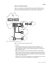
APPN Connection Network
When nodes are attached to a shared-access transport facility (SATF), any-to-any
connectivity is possible. This any-to-any connectivity allows direct connections
between any two nodes, eliminating routing through intermediate network nodes
and the corresponding data traversing the SATF multiple times. To achieve this
direct connectivity, however, TGs must be defined on each node for all the other
possible partners.
Defining connections between all possible pairs of nodes attached to the SATF
results in a large number of definitions (increasing on the order of the square of the
number of nodes involved) and also a large number of topology database updates
(TDUs) flowing in the APPN network. To alleviate these problems, APPN allows
nodes to become members of a connection network to represent their attachment to
an SATF. Session traffic between two nodes that have been defined as members of
a connection network can be routed directly, without passing through a network
node (achieves direct connectivity). To become a member of a connection network,
an APPN node’s port must be ″attached″ to a Connection Network by defining a
connection network interface. When the port is defined, a Connection Network TG
is created by the APPN component to identify the direct connection from the port to
the SATF (i.e. the connection network). This TG is not a conventional TG as in the
case of defined link stations, but rather represents the connection to the Connection
Network in the topology database.
APPN
12
MRS V3.2 Protocol Config Ref Vol 2
|
|