


When configuring a DLSw port for APPN on the router, you assign the network
node a unique MAC and SAP address pair that enables it to communicate with
DLSw. The MAC address for the network node is locally administered and must not
correspond to any physical MAC address in the DLSw network.
APPN Frame Relay BAN Connection Network Implementation
The implementation of an APPN Frame Relay BAN connection network allows you
to define an APPN frame relay port that supports the bridged frame relay format
(BAN) to a connection network.
A shared-access transport facility (SATF) is a transmission facility, such as
token-ring or Ethernet, in which nodes attached to the SATF can achieve any-to-any
connectivity. This any-to-any connectivity allows direct connections between two
nodes, eliminating routing through intermediate network nodes and the
corresponding data traversing the SATF many times. TGs must be defined on each
node to all other nodes in order to achieve this direct connectivity.
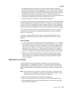
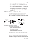
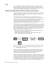
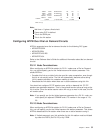
The SATF shown in Figure 4 illustrates that the APPN NN in the router must define
a link station to each node on the token-ring in order to initiate a connection to each
node on the token-ring. The APPN NN must know the DLCI address for the frame
relay link and the MAC address of each node on the token-ring. If the nodes on the
token-ring want to initiate a connection to the APPN NN, they must define a link
station in the APPN NN in the device and specify:
v BAN DLCI MAC address if the device connecting the token-ring to the frame
relay network is performing the BAN function
v The Boundary Node Identifier MAC address if the device connecting the
token-ring to the frame relay network is a bridge
Note: In this diagram and in all the following Frame Relay BAN diagrams, the
APPN resides in the 2210.
Defining connections between all possible pairs of nodes attached to the SATF
results in a large number of definitions and a large number of topology database
update flows on the network. APPN allows nodes to become members of a
connection network to represent their attachment to the SATF.
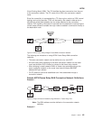
Figure 5 on page 45 shows all nodes as members of the same connection network.
Nodes use the connection network to establish communication with all other nodes,
removing the necessity of creating connections to all other nodes on the SATF. To
become a member of a connection network, an APPN node’s port must be attached
to a connection network by defining a connection network interface. When the port
is activated, a connection network TG is created by the APPN component to a
Figure 4. Logical View with Frame Relay Bridged Frame/BAN Connection Network Support
APPN
44
MRS V3.2 Protocol Config Ref Vol 2