


DEFINITYEnterpriseCommunicationsServerandSystem75andSystem85
Terminals and Adjuncts Reference
555-015-201
Issue 11
December 1999
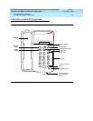
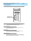
The 6400 Series Telephones
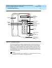
7-7The 6402 and 6402D Telephones
7
Wiring Information
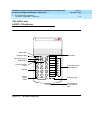
The 6402 and 6402D telephones work in ONLY a 2-wire DCP configuration. The
table below describes the pins on a 6400-Series telephone LINE jack.
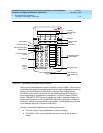
Notes on 6400 Series 2-Wire Installation and Wiring:
ALL wiring between the PBX and the telephone wall jack MUST consist of
twisted-pairs. The line cord must be either a D8W, which consists of 4
twisted-pairs, or a D2R which is a 2-conductor non-twisted pair cord. Only these
cord types have been approved by Lucent Technologies. For optimum
performance, the line cord length should not extend beyond that originally
supplied with the telephone.
A D8W modular cord MUST be used for all 2-wire installations requiring auxiliary
power. If using an auxiliary power supply such as a Lucent Technologies 1151A, it
is acceptable to have a D2R cord connected from the wall jack to the LINE jack
found on the power supply.
For 2-wire operation, if you need to plug the telephone into a 4-pin or 6-pin wall
jack, instead of a standard 8-pin modular jack, refer to the “Line Interface” table
above to insure that the wires from the 4-pin or 6-pin wall jack are connected to
the correct pins on the telephone “LINE” jack.
The 6400 Series telephones can be connected to either a RJ45x or an RJ11C
station jack. If connected to an RJ11C, a 2-wire/4-wire Line Adapter must be
installed. This adapter is available to accommodate situations where customers
need to upgrade from an analog type RJ11C jack to an 8-wire RJ45x type jack.
This adapter only works when using a 6400 Series telephone on either the 2-wire
16-port (TN2181) or the 24-port (TN2224) digital line circuit card.
In 2-wire installations using an RJ45x station jack, PBX connections must be on
pins 4 and 5 and auxiliary power must be connected to pins 7 and 8. In 2-wire
installations using an RJ11C station jack, PBX connections must be on pins 3 and
4 and auxiliary power must be connected on pins 2 and 5.
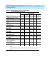
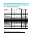
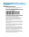
Table 7-1. The Pins on a 6400-Series telephone LINE Jack
Line Interface
Pin Pair Name Description
41 U-T 2-Wire(Tip)
5 1 U-R 2-Wire (Ring)
7 4 P1- Adjunct Power -48V
8 4 P2+ Adjunct Power Common