DEFINITYEnterpriseCommunicationsServerandSystem75andSystem85
Terminals and Adjuncts Reference
555-015-201
Issue 11
December 1999
Cordless and Wireless Telephones
18-3The MDC 9000 Cordless Telephone
18
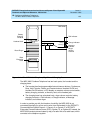
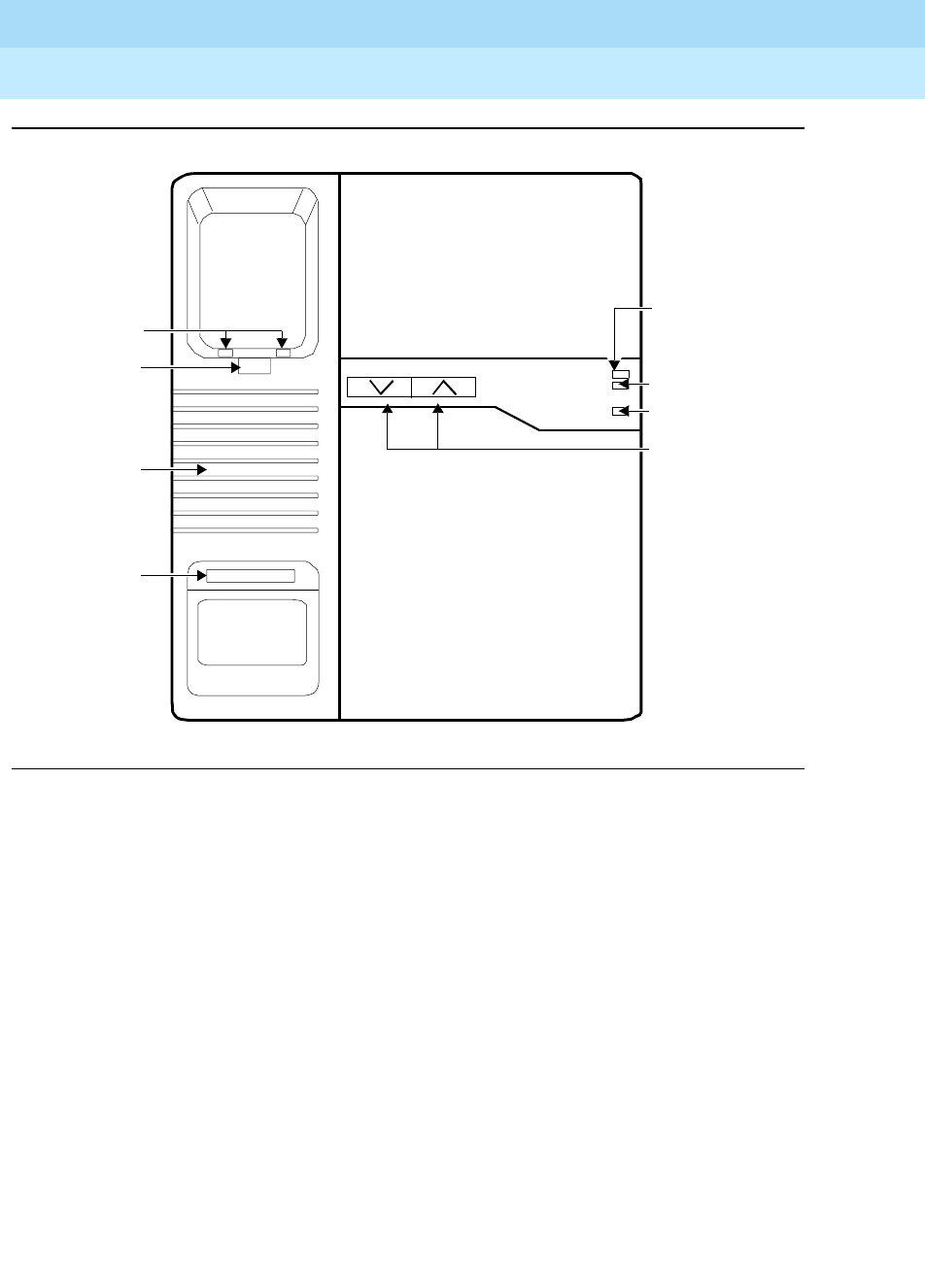
Figure 18-2. The MDC 9000 Telephone, Top View of Charging Base
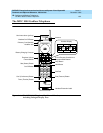
The MDC 9000 Cordless Telephone has two basic parts, the handset and the
charging base.
■ The handset has line/programmable feature/intercom buttons, Conference,
Drop, Hold, Transfer, Status, and Feature buttons, Headset On/Off and
Handset On/Off buttons, a LCD display, an earpiece volume control switch,
battery charging contacts, a directory card, and a headset jack.
■ The charging base has a handset hook, ringer volume controls, battery
charging contacts, a Talk indicator, a Charge indicator, a Message
indicator, and a base ringer.
In order to provide you with the freedom of mobility, the MDC 9000 is not
connected physically (by a line cord or wire from the handset) to the DEFINITY
Communications System Generic 1, Generic 2, or Generic 3, a DEFINITY
Enterprise Communications Server (ECS), System 75, or System 85. Instead, the
MDC 9000 handset communicates by way of a radio link to its radio base, which
connects to the telephone system.
Battery
Ext. 14
Ta l k
Base
MDC 9000
Charge
Message
Ringer Volume
Base Ringer
Handset Hook
Talk Indicator
Charge Indicator
Message
Ringer
Charging
Contacts
Extension
Label
Indicator
Volume
Controls


