


DEFINITYEnterpriseCommunicationsServerandSystem75andSystem85
Terminals and Adjuncts Reference
555-015-201
Issue 11
December 1999
Cordless and Wireless Telephones
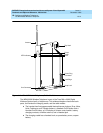
18-18The MDW 9000 Wireless Telephone
18
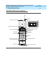
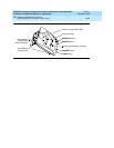
Power Cord Jack
This jack is used for connecting the power cord to your charging cradle. This cord
is then plugged into a wall outlet. This jack is located on the back of the cradle.
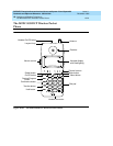
Radio Module Features
Power and Pass Indicator Lights
The Power and Pass lights indicate when the module is powered up and
completes its self-diagnostic. The Radio light goes on when the handset is in use.
Top Hook and Card Edge
The top hook and the card edge connect the radio module to the carrier
assembly/backplane mounting rod.
Snap Lock
This lock locks the radio module into the carrier assembly.
Antenna
The sturdy and flexible antenna sends signals between the handset and the radio
module.
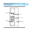
Power Plug Jack
The AC adapter should be inserted into this jack.
Line Jack
The line cord should be inserted into this jack.
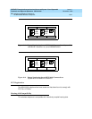
Display Information
The LCD Display provides visual call and telephone status information through
thefollowingsetoficons:
■ or or shows the status of the adjacent button. If the triangle
and rectangle both appear, you are using that line; if only the rectangle
appears, the line is in use.
■ 18 appears during Local Test Mode; 0 through 10 can appear during the
Wireless Test Mode.
■ ON appears when the handset is on.
■ RANGE flashes to indicate that you are out of range and appears steadily
when you have lost communication.
■ P is
not
used with a DEFINITY switch or System 75 or System 85.
■ MUTE appears when the handset microphone is muted.