DEFINITYEnterpriseCommunicationsServerandSystem75andSystem85
Terminals and Adjuncts Reference
555-015-201
Issue 11
December 1999
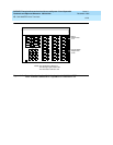
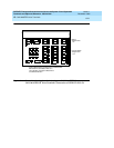
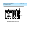
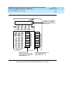
CALLMASTER Voice Terminals
13-16
13
The design of this product allows it to operate on either 2-wire or 4-wire DCP circuits. In
order for the terminal to function properly in either 2-wire or 4-wire installations, there
must be NO INTERCONNECTIONS between the wire pairs used for 2-wire and 4-wire
operation. Bridging or paralleling of these pairs can result in damage to the terminal or
can cause the PBX circuit pack to remove power to the terminal.
REMOVE ALL CONNECTIONS BETWEEN PAIRS BEFORE CONNECTING THE
TERMINAL.
For 2-wire operation, if you need to plug the voice terminal into a 4-pin or 6-pin wall jack,
instead of a standard 8-pin modular jack, refer to the “Modular Wall Jack Wiring” table on
the next page to insure that the wires from the 4-pin or 6-pin wall jack are connected to
the correct pins on the terminal 2-wire “LINE” jack.
4-WIRE installations MUST ONLY have PBX connections on pair 2 and pair 3 and, if
necessary, auxiliary power must be connected to pair 4.
2-WIRE installations MUST ONLY have PBX connections on
pair 1 and, if necessary,
auxiliary power must be connected to pair 4.
Wiring Note for the CALLMASTER VI
All wiring between the DEFINITY ECS and the CALLMASTER VI, including the
line cord, must consist of twisted pairs. Twisted-pair wiring makes lines less
sensitive to crosstalk. The line cord must be a D8W, which consists of four twisted
pairs, or a Lucent Technologies-approved equivalent.
Distance Limitations
The maximum allowable distances the CALLMASTER voice terminals can be
located from the DEFINITY G1, G2, and G3, DEFINITY ECS, System 75, or
System 85 cabinet is shown in the table below.
NOTE:
The 602 CALLMASTER can be connected to any of the switches listed
directly above. However, the CALLMASTER II and CALLMASTER III are
only supported when connected to a DEFINITY G3. The CALLMASTER IV
is supported only when connected to a DEFINITY G3V3.


