DEFINITYEnterpriseCommunicationsServerandSystem75andSystem85
Terminals and Adjuncts Reference
555-015-201
Issue 11
December 1999
CALLMASTER Voice Terminals
13-15
13
Wiring Information on the CALLMASTER IV
The CALLMASTER IV voice terminal works in both 4-wire and 2-wire DCP
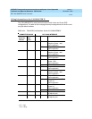
configurations. The table on the next page shows pin assignments for the line cord
and jack block interface
*U-T=“Tip”
U-R = “Ring”
Table 13-1. The DCP Line Interface for the CALLMASTER IV
CONNECTOR BLOCK DCP JACK INTERFACE
Conn.
Block Pin
Number
DInside
Wire
Color
Pin Name Signal Description
3 W-O 1 OD1 Balance output from
telephone (power –48V)
4-wire application
REC-1 Output to Recorder
2-wire application
4 O-W 2 OD2 Balance output from
telephone (power –48V)
4-wire application
REC-2 Output to Recorder
2-wire application
5 W-G 3 ID1 Balance input from PBX
(power –48V)
4-wire application
2-wire — unused
1 W-BL 4 REC-1 Output to Recorder
4-wire application
U-T* Balanced output from
telephone (power –48V)
2-wire application
2 BL-W 5 REC-2 Output to Recorder
4-wire application
U-R* Balanced output from PBX
(power 0v)
2-wire application
6 G-W 6 ID2 Balanced input from PBX
(power 0v)
4-wire application
2-wire — unused
7 W-BR 7 P1– Adjunct power –48V
(to Adjunct jack)
8 BR-W 8 P2+ Adjunct power common
(to Adjunct jack)


