DEFINITYEnterpriseCommunicationsServerandSystem75andSystem85
Terminals and Adjuncts Reference
555-015-201
Issue 11
December 1999
Data Modules
21-25The 8400B Plus Data Module
21
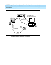
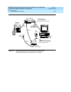
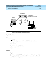
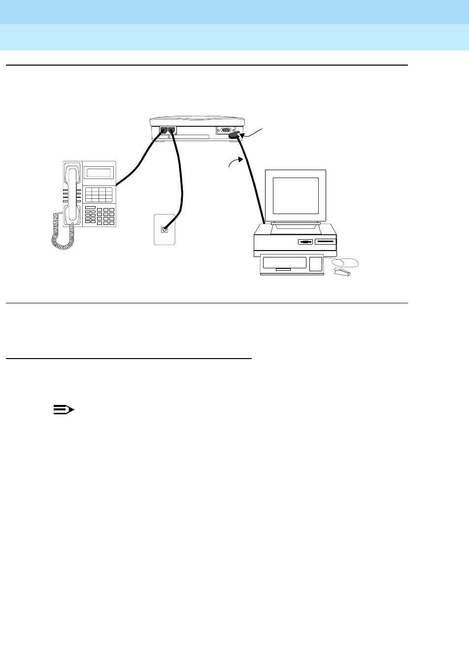
Figure 21-8. Typical Installation of the US and International Configuration,
Including Telephone and Closet Power Supply
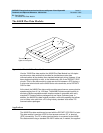
Physical Description
Dimensions
NOTE:
The following measurements for the 8400B Plus data module are
approximate.
Width = 5 inches
Depth (front and rear) = 7-3/4 inches
Height = 1-1/4 inches
Features
Lights
The front panel of the 8400B Plus has two lights, one red light and one green light.
These lights indicate the status of the set during normal operation and the result
of self-tests when initially powered.
PHONE
LI NE/
PO WE R
!
USE ONLY WITH COMMUNICATION
CIRCUIT POWER SOURCE
(Rear Endplate)
Wall
D8W
EIA-232-D
D8W
M9/F25 Adapter
(use only with 25-pin
EIA-232-D Connector Cord)
(9-pin or
25-pin)
Connector
Cord
Jack
Telephone
(Optional)


