DEFINITYEnterpriseCommunicationsServerandSystem75andSystem85
Terminals and Adjuncts Reference
555-015-201
Issue 11
December 1999
Cordless and Wireless Telephones
18-15The MDW 9000 Wireless Telephone
18
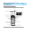
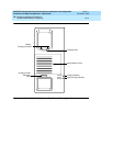
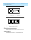
■ The radio module has Power, Pass, and Radio indicator lights, a top hook,
card edge, and snap lock which connect the radio module to the carrier
assembly/backplane, an antenna, and power plug and line connectors.
In order to provide you with the freedom of mobility, the MDW 9000 is not
connected physically (by a line cord or wire from the handset) to the DEFINITY
Communications System Generic 1, Generic 2, or Generic 3, or the DEFINITY
ECS. Instead, the MDW 9000 communicates by way of a radio link to its matched
radio module, which, in turn, connects it to the DEFINITY switch or the DEFINITY
ECS. The telephone needs merely an electrical outlet, and a test check to make
sure that the handset is in range of its matching radio module.
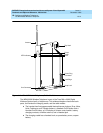
The handset communicates through a matching radio module. When up to six
wireless phones are used within a single location, a carrier assembly is required.
When the radio modules are placed in the carrier assembly, it is considered a
radio base station.
Applications
The MDW 9000 Wireless Telephone can be used with the DEFINITY
Communications System Generic 1, Generic 2, and Generic 3, the DEFINITY
ECS, System 75, and System 85.
Physical Features
Dimensions
NOTE:
The dimensions described here for the MDW 9000 telephone are
approximate.
For the Handset:
Width = 1.5 inches
Length = 10 inches
Height = 2.43 inches
For the Cradle:
Width = 3.94 inches
Length = 9.75 inches
Height = 5.13 inches


