DEFINITYEnterpriseCommunicationsServerandSystem75andSystem85
Terminals and Adjuncts Reference
555-015-201
Issue 11
December 1999
Cordless and Wireless Telephones
18-19The MDW 9000 Wireless Telephone
18
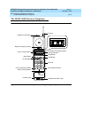
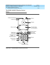
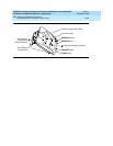
■ T appears when the Wireless Test Mode is active.
■ MSG appears when there is a message waiting for you.
■ BATT appears when the battery is low.
Out-of-Range Indication
While the set is still active, it gives an audible indication (double beep) and visual
indication (the RANGE icon appears on the LCD display) when the handset is
getting out of range of the radio module.
Distance and Installation Limitations
The MDW 9000 uses radio transmissions to communicate. The range depends on
your particular operating environment. For indoor use, intervening walls will
reduce the phone’s range. Try to stay away from concentrations of structural
metal, such as steel and aluminum, or reinforced concrete.
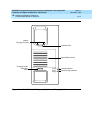
At least 6 feet is required between the radio module/radio base station and the
phone system switch.
Before you install the radio module or radio base station, note the following
considerations:
■ When positioning the radio module or radio base station, try to place the
unit in a central location, relative to the handset usage area. If your switch
is located in a distant area, you may have to run line cord from your phone
system to the centrally positioned radio module(s). The maximum distance
is 1000 feet of 26 gauge cable.
■ The radio module or radio base station should not share the same power
line or be within 6 feet of equipment with microprocessors such as
answering machines, personal computers, and fax machines, or
electromagnetic equipment such as electric motors.
■ For remote locations, an individual radio module can be installed in that
area and attached via line cord to the phone system. IROBs should be
used in outdoor area.
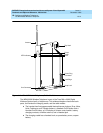
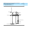
■ The radio module or radio base station should be placed high on the wall
for optimum voice quality and range. Allow at least 1 foot of space between
the top of the antenna on the radio module(s) and the ceiling.
■ Install the single radio module within 3 feet of either side of, and within
6-8 feet above, a properly grounded 3-prong electrical outlet that is not
controlled by an on/off switch.
■ Install the radio base stations within 15 feet of either side of, and within
6-8 feet above, a properly grounded 3-prong electrical outlet that is not
controlled by an on/off switch.


