


DEFINITYEnterpriseCommunicationsServerandSystem75andSystem85
Terminals and Adjuncts Reference
555-015-201
Issue 11
December 1999
Data Modules
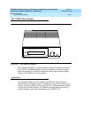
21-34The 7500B Data Module
21
■ Synchronous half-duplex emulation at 1.2 to 56 kbps
■ Automatic answering of incoming data calls
■ RS-366 ACU interface
■ Autodial
The synchronous DCE features with the High Speed Synchronous Enhancement
Board are as follows:
■ V. 3 5 i n t er fa c e
■ Circuit switched or nailed-up data communication
■ Data rates of 48, 56, and 64 kbps
■ Full-duplex operation at all speeds
■ Synchronous half-duplex emulation at 56 kbps only
■ Automatic answering of incoming data calls
■ Autodial
Distance Limitations
The maximum signaling distance from the port board to the work location jack
based on DIW 24 AWG cable is:
■ Terminating resistor in work location — 1,900 feet
■ Terminating resistor in satellite closet — 1,600 feet
Power Requirements
The stand-alone 7500B Data Module operates with power from a modular AC to
DC adapter that is normally plugged into a wall outlet. When the 7500B is used in
a multiple mount arrangement, a built-in power supply is provided in the 77A Data
Mounting.
Terminating Resistor
A 440A4 Terminating Resistor adapter is required with the 7500B. The 440A4 can
be located at the work location or in the satellite closet.
FCC Registration
The 7500B data module is not FCC registered.
Additional Documents
The following documents contain additional information relating to the 7500B Data
Module:
7500B Data Module User’s Manual
, 555-021-717