


CDM-Qx Satellite Modem Revision 5
Front Panel Operation MN/CDMQx.IOM
5–62
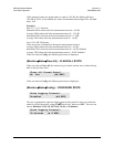
This sub-menu permits the user to select the following test modes:
Norm
(Normal) This clears any test modes or loopbacks, and places the unit back into an
operational state.
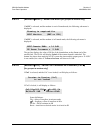
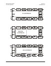
IF Loop
(IF Loopback) This test mode invokes an internal IF loop. This is a particularly useful
feature, as it permits the user to perform a quick diagnostic test without having to
disturb external cabling. Furthermore, all of the receive configuration parameters are
temporarily changed to match those of the transmit side. When Normal is again
selected, all of the previous values are restored. During an IF Loop, the Tx carrier
continues to be transmitted. See Figure 5-4.
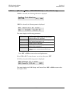
Dig Loop
(Digital Loopback) This test mode invokes a digital Loopback, which loops data at the
output of the framer/scrambler on the transmit side, back into the deframer/descrambler
on the receive side. If concatenated Reed-Solomon FEC is being used, this is also
included in the digital loop. See Figure 5-4.
I/O Loop
(Inward/Outward Loopback) This test mode invokes two distinct loopbacks. The first
of these is the inward loop, which takes data being received from the satellite direction,
and passes it directly to the modulator. Simultaneously, the outward loop is invoked,
whereby data being fed to the transmit data interface is routed directly back out of the
receive data interface. See Figure 5-4.
RF Loop
(RF Loopback) This test mode is almost identical to the IF loop mode. All of the
receive configuration parameters are temporarily changed to match those of the
transmit side, however, no internal connection is made. This is useful for performing a
satellite Loopback. When NORMAL is again selected, all of the previous values are
restored.
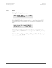
TX-CW
(Transmit CW) This is a test mode, which forces the modulator to transmit a pure
carrier (unmodulated). Used for measuring phase noise.
TX-1,0
(Transmit an alternating 1,0,1,0 pattern) This is a test mode that forces the modulator
to transmit a carrier modulated with an alternating 1,0,1,0 pattern, at the currently
selected symbol rate. This causes two discrete spectral lines to appear, spaced at +/-
half the symbol rate, about the carrier frequency. This mode is used to check the carrier
suppression of the Modulator. If OQPSK is selected as the modulation type, the test
will produce a spectral pattern suitable for the measurement of SSB rejection – useful in
determining the phase and amplitude accuracy of the modulator.