CDM-Qx Satellite Modem Revision 5
Preface MN/CDMQx.IOM
iv
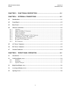
CHAPTER 3. FUNCTIONAL DESCRIPTION .......................................................... 3–1
CHAPTER 4. EXTERNAL CONNECTIONS ............................................................ 4–1
4.1 Introduction................................................................................................................................4–1
4.2 Front Panel .................................................................................................................................4–2
4.3 Rear Panel ..................................................................................................................................4–3
4.4 Chassis Connections ..................................................................................................................4–5
4.4.1 USB Port .............................................................................................................................4–5
4.4.2 M&C 10/100BaseT Connector............................................................................................4–5
4.4.3 485/232 Connector..............................................................................................................4–5
4.4.4 Alarms Connector ...............................................................................................................4–6
4.4.5 Balanced G.703 Connector Tx/Rx Connector.....................................................................4–7
4.4.6 Unbalanced G.703 Tx/Rx Connectors ...............................................................................4–7
4.4.7 RS-530 Data Interface Connector .......................................................................................4–8
4.4.8 RX and TX IF Connectors ..................................................................................................4–9
4.4.9 Ref Connector .....................................................................................................................4–9
4.5 AC Power Connector.................................................................................................................4–9
4.6 DC Power Connector.................................................................................................................4–9
4.7 Ground Connector...................................................................................................................4–10
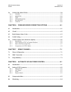
CHAPTER 5. FRONT PANEL OPERATION ........................................................... 5–1
5.1 Introduction...............................................................................................................................................5–1
5.2 Left-Hand Display Area............................................................................................................................5–4
5.2.1 Modems .............................................................................................................................................5–4
5.2.2 Redundancy .......................................................................................................................................5–5
5.2.3 Spectrum Analyzer ............................................................................................................................5–5
5.3 Right-Hand Display Area .........................................................................................................................5–6
5.4 Accessing the Display Area.......................................................................................................................5–6
5.5 Opening Screen..........................................................................................................................................5–8


