A
–1
Appendix A. SUMMARY OF
SPECIFICATIONS
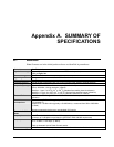
A.1 Modulator
Note: Features not in the initial product release are identified in parentheses.
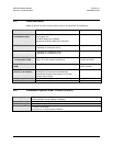
Modulation
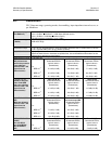
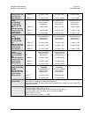
See Table A-5
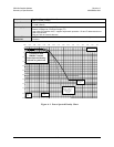
Symbol rate range
Up to 10 Msps (lower end is modulation and FEC rate dependant)
Refer to Figure A-1.
Data rate range
See Table A-5
Operating modes
Transparent, closed network, DoubleTalk™ Carrier-in-Carrier®
FEC
See Table A-5
Transmit filtering
Per INTELSAT IESS-308 (0.35) or 0.20 (for use with closer adjacent channel spacing)
Scrambling
V.35 or synchronous
Output frequency
50 to 90, 100 - 180 MHz, 100 Hz resolution (70/140 MHz IF)
950 to 1950 MHz, 100 Hz resolution (L-Band)
Stability ± 1 ppm, 0 to 50
o
C (32
o
to 122
o
F) (standard low-stability internal reference)
Stability ± 0.1 ppm, 0 to 50
o
C (32
o
to 122
o
F) (Optional high-stability internal reference)
Stability ± 0.1 ppm, 0 to 50
o
C (32
o
to 122
o
F) (standard reference for L-Band)
External Reference
1, 2, 5, 10, or 20 MHz @ 0 dBm to +20 dBm. Internal reference phase locks to external
reference.
Harmonics
and spurious
Greater than -55 dBc/4 kHz (typically <-60 dBC/4kHz) – measured from 25 to 400 MHz
(70/140MHz IF)
Greater than -55 dBc/4 kHz (typically <-60 dBC/4kHz) – measured from 500 to 2500 MHz
(L-Band)
Spurious measured relative to an unmodulated (CW) carrier
Transmit On/Off
Ratio
55 dB minimum
Output phase noise
< 0.48
0
rms double sided, 100 Hz to 1MHz
(minimum of 10 dB better overall than the INTELSAT IESS-308/309 requirement)
Output power
-5 to -25 dBm, 0.1 dB steps (70/140MHz IF)
-5 to -45 dBm, 0.1 dB steps (L-Band).
Refer to Automatic Uplink Power Control section.
Power accuracy
±1.0 dB over frequency, temperature, and number of modulators installed in the chassis


