


CDM-Qx Satellite Modem Revision 5
External Connections MN/CDMQx.IOM
4–3
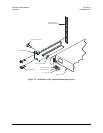
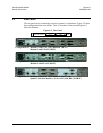
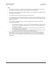
4.3 Rear Panel
The rear panel can be customized to meet the customer’s requirements. Figure 4-2 shows
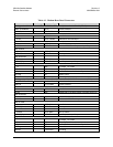
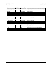
three configurations that are available. Table 4-1 lists these connectors and Figure 4-2
shows the locations.
Figure 4-2. Rear Panel
Slot 1
Slot 2
Slot 3
Slot 4
IF I/OPrime Power & Control
Configuration #1 Modem 1 with G.703 T1/E1 Balanced (DB-15)
Modem 2 with EIA-422 (DB-25)
Configuration #2 Modem 1 with G.703 T1/E1 Unbalanced (BNC)
Modem 2 with EIA-422 (DB-25)
Configuration #3 Modem 1 with G.703 T1/E1 Balanced (DB-15) and
Quad E1 Interface Module, 1-4 Ports of E1,with D&I (2) DB-9F)