


CDM-Qx Satellite Modem Revision 5
CnCPerformance Characterization MN/CDMQx.IOM
D–8
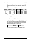
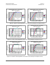
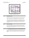
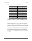
Figure D-8. CnC Ratio For 16-QAM
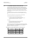
D.5 Symbol Rate Ratio
CnC operation is restricted to a maximum symbol rate ratio ≤3. This is the ratio of the
larger carrier to the smaller one. Within these limits, the performance characterized
applies. The limitation on the symbol range still allows a wide range of data rates.
It is necessary to take into account the symbol rate ratio to properly estimate the CnC
ratio, although the modem does this automatically. For estimating the link parameters,
the CnC ratio is adjusted by 10 Log (Symbol Rate Ratio). If the symbol rate ratio is 2.0
then the narrower carrier has a 3 dB CnC ratio when the CnC carriers have the same
spectral density.
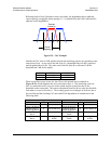
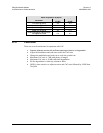
D.6 CnC Carrier Offset
CnC carriers are normally placed directly on top of each other with the same center
frequency for both carriers. Normal operation is obtained when the center frequency of
the two carriers is within ± 32 kHz. This is the same as the normal acquisition range of
the modem for standard and CnC carriers.
D.7 1
st
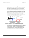
CnC Example: Adjacent Carriers, CnC Ratio and Rain Fade
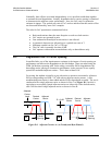
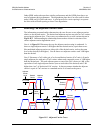
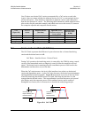
As an example, a pair CnC carriers is flanked by two adjacent CnC pairs with a carrier
spacing of 1.3 x Symbol Rate and the power level is the same for all carriers as shown in
Figure D-9. In this scenario, the modulation is 8-PSK 3/4 Turbo with identical data
rates.
Eb/No Degradation (vs) CnC Ratio (16-QAM)
-2.0
-1.8
-1.6
-1.4
-1.2
-1.0
-0.8
-0.6
-0.4
-0.2
0.0
-10 -5 0 5 10
CnC Ratio (dB)
Eb/No Degradation (dB
)
16-QAM 3/4 Turbo
16-QAM 7/8 Turbo