


CDM-Qx Satellite Modem Revision 5
External Connections MN/CDMQx.IOM
4–12
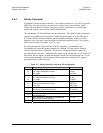
4.4.9 RX and TX IF Connectors
The IF connectors will depend on the configuration ordered. The following reflects
configurations available. BNC 75Ω is standard for 70/140MHz IF, N-Type 50Ω for L-
Band, and BNC Ref Connector. This 50Ω BNC female connector provides an external
reference input for the Tx and Rx IF synthesizers, and for the internal transmit clock.
The load impedance is 60.4Ω, so the VSWR is less than 1.25:1 at either 50Ω or 75Ω.
Input level is 0 dBm minimum to +20 dBm maximum at either 1, 2, 5, 10, or 20 MHz.
When external reference is enabled, the internal 10 MHz reference oscillator is phase
locked to the external reference input by a 10Hz bandwidth PLL. If no activity is present
at the external reference input, the modem will revert to the internal 10 MHz reference.
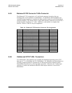
4.5 AC Power Connector
A standard, detachable, non-locking, 3-prong power cord (IEC plug) supplies the
Alternating Current (AC) power to the modem. Observe the following:
AC Power Specifications
Input Power 290W maximum, 57W typical without BUC power supply.
Input Voltage 100 - 240 volts AC, +6%/-10% - autosensing
(total absolute max. range is 90 to 254 VAC)
Connector Type IEC
Fuse Protection 3.15A Slow-blow
Line and neutral fusing
20 mm type fuses
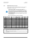
4.6 DC Power Connector
A standard, 3-screw terminal block supplies the Direct Current (DC) power to the
modem. Observe the following:
AC Power Specifications
Input Power 290W maximum, 57W typical without BUC power supply.
Input Voltage 36 to 72 VDC; 6.25 amps
Connector Type Terminal Block
Fuse Protection 3.15A Slow-blow
20 mm type fuses