


CDM-Qx Satellite Modem Revision 5
CnCPerformance Characterization MN/CDMQx.IOM
D–9
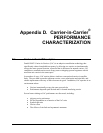
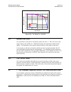
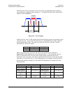
Referring back to Error! Reference source not found., the degradation due to adjacent
carrier spacing is negligible when spacing is 1.3 x Symbol Rate and 0 db is allocated for
adjacent carrier degradation.
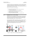
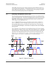
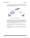
Figure D-9. CnC Example
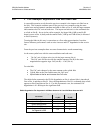
Initially the CnC ratio is 0 dB, and the desired and interfering carriers are operating at the
same power level. At one end of the link (Site A), a downlink fade of 4 dB is expected
and an uplink fade of 6 dB. The other end of the link (Site B) is allocated 2 dB for
downlink and 3 dB for the uplink:
DL Fade UL Fade
Site A
4 dB 6 dB
Site B
2 dB 3 dB
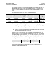
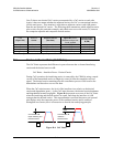
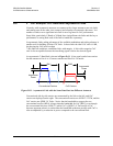
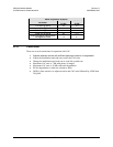
When a rain fade occurs at one site, the effect is felt at both sites as outlined in
Figure D-10, which diagrams the worst case fade at Site A. The interfering carrier at
Site A is attenuated twice, once due to the uplink and the second time due to the
downlink on the return path. The carrier transmitted from Site B sees only the downlink
fade when it is received at Site A. The resulting power level changes at each site due to
the rain fade and the resulting CnC ratio and Eb/No degradation is summarized in the
following table:
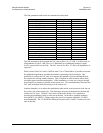
Site A Site B
Parameter dB Comment Parameter dB Comment
Relative Level of
Carrier A @ Site A
-10 Due to fade at A Relative Level of
Carrier B @ Site B
0 Due to fade at A
Relative Level of
Carrier B @ Site A
-4 Due to fade at A Relative Level of
Carrier A @ Site B
-6 Due to fade at A
CnC Ratio At
Site A
-6 CnC Ratio At
Site B
+6
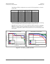
Degradation At
Site A
-0.1
Per Figure D-
8-PSK
Degradation At
Site B
-0.3
Per Figure D-
8-PSK
Desired
Carrier(s)
Carrier
Spacing