


CDM-Qx Satellite Modem Revision 5
External Connections MN/CDMQx.IOM
4–4
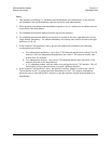
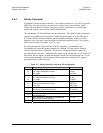
Notes:
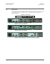
1. One interface per Modem (i.e. Modulator and Demodulator card combination) or one interface
per Modulator card and Demodulator card are required if used independently.
2. When grouping a modulator and demodulator together to use as a modem, the modulator must be
located above the demodulator.
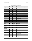
3. For redundant operation the backup unit does not need an interface.
4. For redundant operation the backup unit needs to be located in the lower right hand slot (#4) for
single module redundancy. For modem redundancy the backup units must be located in the right
hand slots (#3 & #4).
5. In the example Configuration #1 above, because all modules have interfaces, the following
configurations are possible.
a. Two independent modulators - one with a G.703 balanced and the other with an EIA-530
interface, with two independent demodulators one with a G.703 balanced and the other
with an EIA-530 interface.
b. Two independent modems - one with a G.703 balanced and the other with an EIA-530
interface (located on the demodulators).
c. A 1:1 redundant modem, with the online unit configured with a G.703 interface. The off
line modules will provide the backup even with a different interface.
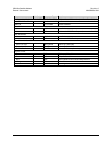
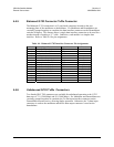
6. In the example Configuration #3 above, the Quad E1 Interface Module is used in slot 3 and 4.
The modulator in slot 1 is grouped with the demoduletor in slot 2. This unique combinations
allows the user to select the Quad E1 interface or the data interface located in the modulator or
demodulator.