


CDM-Qx Satellite Modem Revision 5
CnCPerformance Characterization MN/CDMQx.IOM
D–6
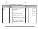
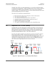
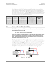
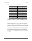
Case D shows two desired CnC carriers accompanied by a CnC carrier on each side.
Again, it does not matter whether the adjacent carriers are CnC or conventional carriers,
just the total power. This situation is equivalent to adjacent carriers each 6 dB greater
than the one desired CnC carrier. The following table summarizes which adjacent carrier
plot to select for this particular example, and which ones to use with a ratio, R, between
the composite adjacent and composite desired carriers.
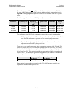
Case
(Figure D-5)
Desired
Carrier
Adjacent Carrier
(See Note)
Curve To Use In
Figure D-2, Error!
Reference source not
found., or D-4
Curve To Use
For Any Ratio
R (dB)
A 1 Carrier 1 Adjacent Carrier 0 dB R - 3 dB
B 1 Carrier 2 Adjacent Carriers +3 dB R + 0 dB
C 1 CnC Carrier 1 Adjacent Carrier +3 dB R + 0 dB
D 1 CnC Carrier 2 Adjacent Carriers +6 dB R + 3 dB
Note: The adjacent carrier is the composite power for either a conventional carrier or CnC. carrier.
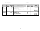
D.4 Carrier-in-Carrier Ratio (CnC Ratio)
The CnC Ratio represents the difference in power between the co-located interfering
carrier and the desired carrier in dB.
CnC Ratio = Interferer Power - Desired Carrier
During CnC operation, the interfering carrier is removed by the CDM-Qx using a stored
version of the transmitted carrier to adaptively cancel it from the composite received
signal. The desired carrier remaining after the cancellation process is delivered to the
demodulator and decoder to recover the data.
When the CnC ratio increases, the level of the interferer rises relative to the desired
carrier and degradation grows. As the CnC ratio decreases, the desired carrier dominates
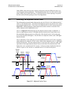
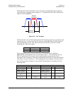
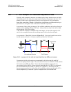
and degradation becomes negligible. Figure D-6 represents two cases of the CnC Ratio
when the interfering and desired carriers are equal, and when the interferer is 6 dB
stronger than the desired carrier. This representation is artificial because a real spectral
plot displays only the composite power of the combined carriers and is unable to
distinguish two carriers, but it is instructive to describe the underlying principle.
Figure D-6. CnC Ratio
CnC Ratio = 0 dB
Equal Interfering And
Desired Carriers
A
CnC Ratio = 6 dB
Interferer >
Desired Carrier
B
+6 dB