


CDM-Qx Satellite Modem Revision 5
Front Panel Operation MN/CDMQx.IOM
5–30
being slightly different from the local clock (a so-called plesiochronous offset), and to
the motion of the satellite (a Doppler offset). The input to the buffer will be the signal
from the satellite, with any clock offsets and jitter. The output from the buffer will be
derived from the local TRANSMIT clock. In this way, the receive data will be perfectly
synchronous with this local clock. The modem operates with independent receive and
transmit data rates. Even in this configuration, where RX data rate <> TX data rate, the
output clock for the buffer will be phase locked to the transmit clock.
While it is only possible to select the size in bits, the corresponding total buffer size is
displayed in ms (which will vary in inverse proportion to the data rate).
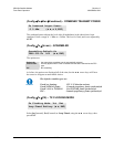
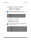
(ConfigRxInv) – RX INVERSION FUNCTIONS
Select Spectrum, Data, or Clock using the ◄ ► arrow keys, then press ENT.
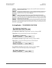
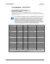
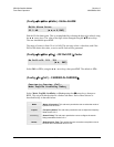
If Spectrum is selected, the following sub-menu will be displayed:
Select Normal or Inverted, using the ◄ ► arrow keys, then press ENT.
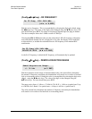
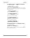
If Data is selected, the following sub-menu will be displayed:
Select Normal or Inverted, using the ◄ ► arrow keys, then press ENT.
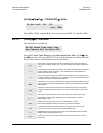
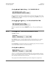
If Clock is selected, the following sub-menu will be displayed:
Select Normal or Inverted, using the ◄ ► arrow keys, then press ENT.
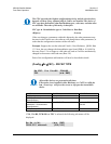
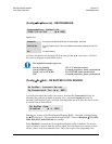
(ConfigRxMisc) – Rx Miscellaneous
Select EbNo or Rx
α using the WXarrow keys, then press ENT.
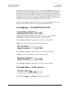
Rx Inversion functions:
Spectrum Data Clock (◄ ►, ENT)
Rx Spectral Inversion:
Normal Inverted (◄ ►,ENT)
Rx Data Sense:
Normal Inverted (◄ ►, ENT)
Rx Clock Inversion:
Normal Inverted (◄ ►, ENT)
Rx Misc: EbNo Rxα
(◄ ►, ENT)