


CDM-Qx Satellite Modem Revision 5
Front Panel Operation MN/CDMQx.IOM
5–5
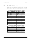
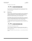
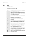
Two modems can share a modem:
The selected modem is the modulator demodulator pair on the right side of the chassis
(when viewed from the back). When modem is in CnC™ mode, the brackets (<>) will
turn into bold characters.
5.2.2 Redundancy
Modules, (modulators and demodulators) can be upgraded to operate as redundant units.
If enabled the module can back up a like kind module located anywhere in the chassis. If
a modulator and demodulator have redundancy enabled and they are grouped as a
modem, the pair can back up a modem. Note: The interface selected for the modules
does not have to match the interface type used on the prime modules.
Three redundancy modes are possible with a modem. Back-up devices are notated with a
B suffix while the designated prime modules (non-modem grouped) are noted with P
suffix. In a non-modem configuration, the back-up device must be installed in slot #4. If a
backup device has failed, the B suffix and the F suffix will alternately display.
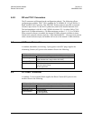
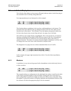
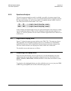
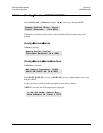
1:1 redundant modems look similar to the two-modem example. The modems have
independent monitor functions, but configuring the prime modem will configure the back
up modem.
In this example, the backup modem is selected.
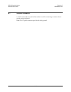
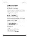
1:2 and 1:3 modulators or demodulators look similar to the basic display. A backup
modulator or demodulator will back up all compatible modulators or demodulators in the
chassis designated as primes.
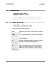
The Online LED together with the selection bracket (<>) is used to indicate which device
is online.
MD <MD> | (right hand display area)
| (right hand display area)
MD <MDB> | (right hand display area)
| (right hand display area)