


CDM-Qx Satellite Modem Revision 5
External Connections MN/CDMQx.IOM
4–9
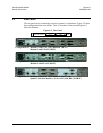
4.4.5 Balanced G.703 Connector Tx/Rx Connector
The Balanced G.703 connection is a 15-pin female connector located on the rear
mounting plate of the modulator or demodulator. If a Modulator and Demodulator are
vertically grouped together as a modem, the data interface connector on the Demodulator
switches to duplex. This feature allows a single data interface connection to be used for a
modem instead of needing a “Y” cable. Otherwise, each module is a simplex data
interface. Refer to Table 4-4 for pin assignments.
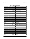
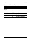
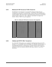
Table 4-4. Balanced G.703 Interface Connector Pin Assignments
Pin # Signal Function Name Direction
1 Drop Data Input ( - ) DDI– In
9 Drop Data Input (+) DDI+ In
2 Ground GND
10 Not Used
3 Insert Data Output ( - ) IDO– Out
11 Insert Data Output (+) IDO+ Out
4 Ground GND
12 Drop Data Output ( - ) DDO– Out (D&I Only)
5 Drop Data Output (+) DDO+ Out (D&I Only)
13 Insert Data Input ( - ) IDI– In (D&I Only)
6 Insert Data Input (+) IDI+ In (D&I Only)
14 Not Used
7 Not Used
15 Not Used
8 Not Used
4.4.6 Unbalanced G.703 Tx/Rx Connectors
Two female BNC 75Ω connectors are available for unbalanced operation at the G.703
data rates of T1 (1.544 Mbps) and E1 (2.048 Mbps). If a Modulator and Demodulator are
vertically grouped together as a modem, the Tx data input interface connector on the
Demodulator becomes active, allowing duplex operation. Otherwise, the Tx data input
connector is used on the modulator and the Rx data output connector is used on the
demodulator.